
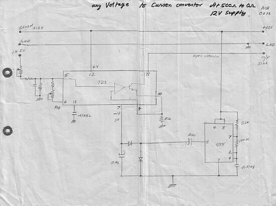
voltage to current convertor
The circuit effectively facilitates the conversion of voltage signals into current signals, which is essential for many industrial applications where current loops are standard. The LM723 operational amplifier is a versatile component that provides stable performance in this configuration. The use of an open collector output allows for easy integration into existing systems without the need for complex interfacing.
The design includes an attenuator that can be finely adjusted to ensure accurate scaling of the input voltage range. This is particularly useful in scenarios where precise control is necessary, as it enables the conversion of the standard 1-5 V input into the widely accepted 4-20 mA current loop standard. The ability to loop multiple instruments is a significant advantage, as it simplifies wiring and reduces the number of power supplies needed in the system.
The circuit's power supply requirement of up to 24 V is adequate for most industrial applications, and the design allows for the cascading of three instruments, enhancing its utility in complex control systems. The connection to pin 6 for converting a 0-1 V input to a 4-20 mA output further broadens the circuit's application range, making it suitable for various sensors and input devices that operate within this voltage range.
Overall, this voltage-to-current loop converter circuit provides a robust solution for converting control signals in industrial automation systems, ensuring compatibility with a wide range of instruments and devices.his Circuit converts a voltage control output from a Process Controller to be converted into a Current Control if the AC-Drive or Valve needs a Current Control Signal. This is a three wire voltage to current loop converter. The 1-5 V DC is attenuated and fed to pin 5 LM723 opamp section which tries to maintain the same voltage at pin 10 across the
10 E, thereby producing a open collector constant current sink proportional to the 1-5V input. By trimming the attenuator you can scale-calibrate 1-5V input to 4-20mA output for looping many instruments in series, like a controller, recorder or PLC. With a supply voltage upto 24V, three instruments can be looped. The connection to pin 6 is required to convert 0-1 input to 4-20mA. 🔗 External reference
Related Circuits
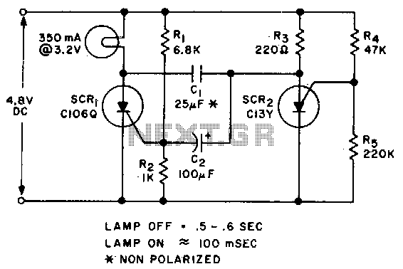
Applying voltage to the circuit triggers SCR1. With SCR1 on, the voltage on the anode of SCR2 rises until SCR2 triggers to commutate SCR1. The voltage on the gate of SCR1 will swing negative at this time, and only...
A voltage-to-frequency converter (VFC) circuit is depicted in the schematic diagram below. The circuit utilizes a 555 integrated circuit (IC) as the core component for its operation. The voltage-to-frequency converter is a crucial component in various analog and digital...
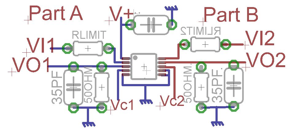
A request for advice regarding the connection diagram of the MAX4685 analog switch is presented. The circuit involves two inputs, VI1 and VI2. The MAX4685 is a low-voltage, dual analog switch designed for low on-resistance and high-speed switching applications. In...
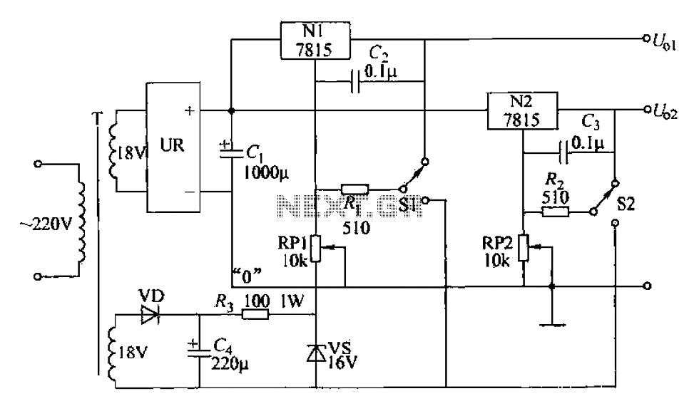
An adjustable dual voltage power supply circuit is presented, suitable for frequent experimental use. The current output does not exceed 1A, and both voltage outputs are adjustable. The circuit utilizes N1, N2, and 78 series three-terminal voltage regulator integrated...
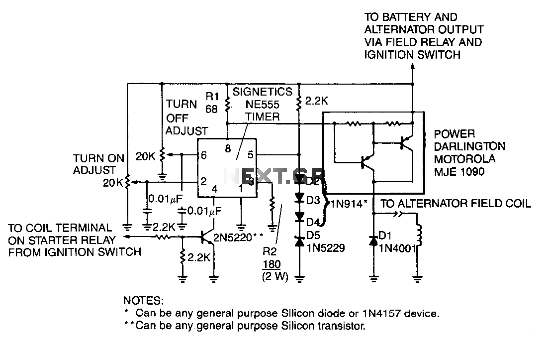
A monolithic 555-type timer serves as the core component of this straightforward automobile voltage regulator. When the timer is inactive, resulting in a low output at pin 3, the power Darlington transistor pair remains off. If the battery voltage...
The schematic of the power supply is illustrated below. It operates using standard household power of 120VAC at a frequency of 50/60Hz, with an adjustable output that can reach up to 25kV or higher. The power supply circuit is designed...