
Many Logic probe circuit ideas

A logic probe is an essential diagnostic instrument in digital electronics, designed to analyze and test the logic levels in digital circuits. It is capable of indicating the presence of high (logic 1) and low (logic 0) signals, as well as providing insights into the state of the circuit under test. Typically, a logic probe consists of a probe tip for direct contact with circuit points, a display (often LED indicators), and a power supply, which may be derived from the circuit being tested or an external source.
The logic probe operates by applying a voltage to the circuit and detecting the resulting logic level. When the probe tip contacts a point in the circuit, it measures the voltage level present. If the voltage exceeds a certain threshold, the probe indicates a logic high; if it falls below that threshold, a logic low is indicated. Some advanced logic probes may also provide additional features, such as pulse width measurement, frequency counting, or the ability to decode specific logic families.
In practical applications, logic probes are invaluable for troubleshooting digital circuits, allowing engineers to quickly determine whether a circuit is functioning correctly or if there are faults present. They are particularly useful for testing integrated circuits, microcontrollers, and digital logic gates, enabling rapid identification of issues without the need for more complex testing equipment. The portability and ease of use of logic probes make them a staple in both educational settings and professional electronics laboratories.Logic probe is useful tool to measure, in a check digital circuits. As a meter, which is used to measure power in electrical circuits. Logic probe was used for.. 🔗 External reference
Related Circuits
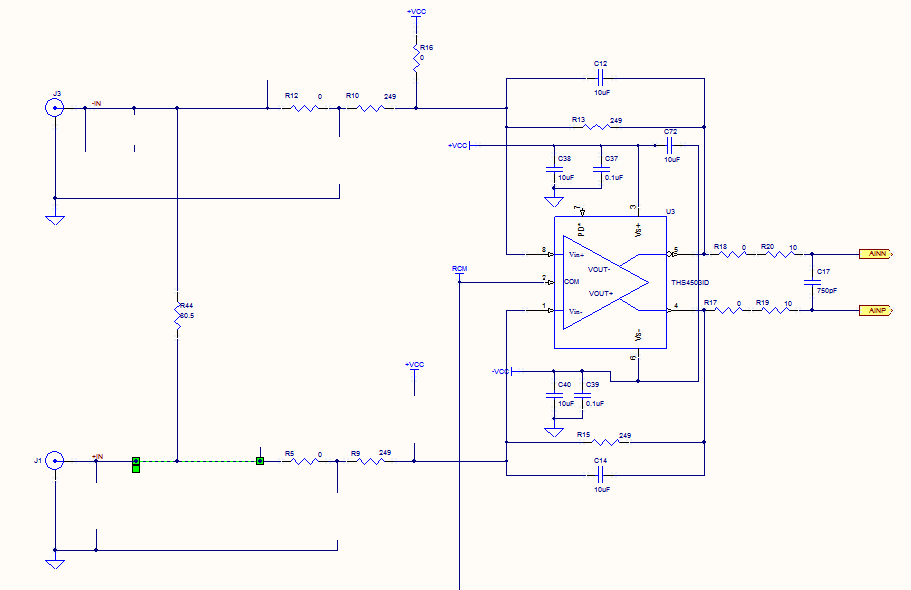
Prior to the test point, there is an AD744 operational amplifier with its output connected to a 10nF capacitor. Following this, a 1kΩ resistor connects to ground. From the junction where the capacitor and resistor meet, a 4.7kΩ resistor...
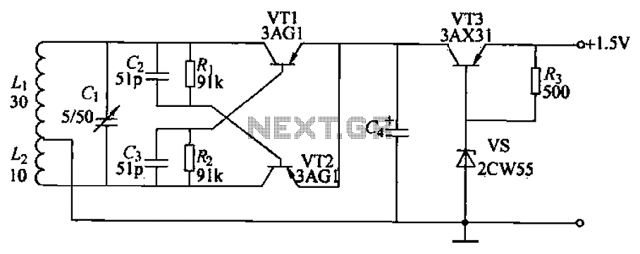
Children often go missing, causing immense suffering and economic losses for families. This situation also presents opportunities for unscrupulous child traffickers to exploit. To address this issue, a radio alarm system has been designed, which consists of a transmitter...
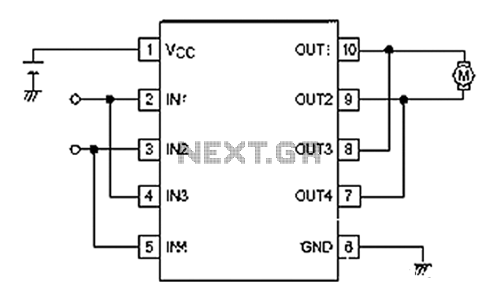
A simple motor control project for forward and backward drive can be implemented using the LB1948M motor driver IC, which features two channels for motor control. The LB1948M is an ideal choice for 12V motor drive systems and can...

This is a simple touch switch circuit where the 555 timer is configured as a one-shot multivibrator triggered by touching the touch terminal. In monostable mode, the timer generates a fixed pulse of approximately 4 seconds whenever the trigger...
This device emits intermittent beeping for approximately two seconds when a whistle is detected within a range of several meters. The first two inverters in IC1 function as audio amplifiers. IC1A consistently amplifies the signal captured by a small...
High pressure alarm with high sensitivity. It detects high-voltage electric energy from 10kV at a distance of 2m or from low-voltage mains (AC 220V) at a distance of 0.3m. The alarm device is simple to manufacture, compact, and user-friendly....