
up down counter circuit
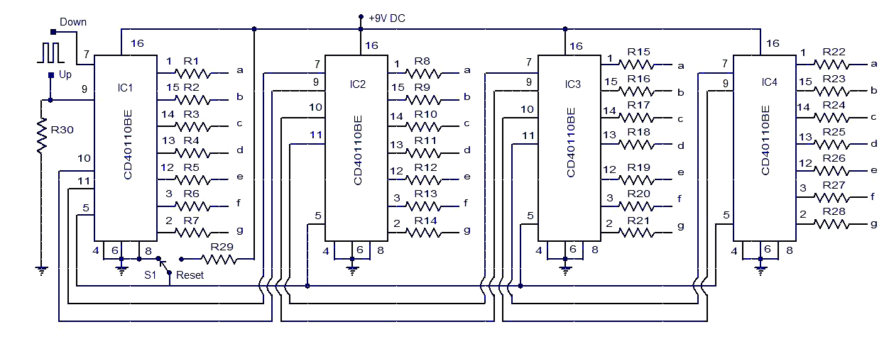
The circuit employs the CD40110BE, which is designed for counting applications and can manage both up and down counting operations. Each IC in this configuration can count from 0 to 9, and by cascading multiple ICs, the overall counting range can be expanded. The common cathode seven-segment displays provide a visual indication of the current count, with each display corresponding to a specific IC in the series.
The connection of the BORROW and CARRY pins between the ICs ensures that the counting process remains synchronized across multiple stages. When the count reaches its maximum value in one IC, the CARRY output triggers the next IC to increment its count. Conversely, when the count decreases to zero, the BORROW signal informs the preceding IC to decrement accordingly. This interconnection is crucial for maintaining the integrity of the counting sequence.
The trigger pulses for counting are essential for the operation of the circuit. The UP counting pulse at pin 7 of IC1 allows the counter to increment, while the down counting pulse at pin 9 facilitates decrementing the count. These pulses can be generated using a push-button switch or a microcontroller, depending on the application's requirements.
The RESET functionality is also a critical aspect of this design. By tying the RESET pins to ground during normal operation, the counter maintains its current state. However, when a reset is needed, activating switch S1 connects the RESET pins to the positive supply, clearing the count and setting all ICs back to zero. This feature is particularly useful for applications requiring a fresh start or recalibration.
Overall, this up/down counter circuit provides a versatile solution for various counting applications, from simple educational projects to more complex industrial control systems. Its design leverages standard IC components and easily integrates with other electronic systems, making it a valuable addition to any electronics toolkit.This is the circuit diagram of a very simple up down counter that can be used of a large number of applications. The circuit is based on the IC CD40110BE which is a CMOS decade up/down counter. For ICs are used here. Common cathode seven segment display is connected to the 7-segment output of each IC. Display connected to the IC1 represents the low est number and display connected to IC4 represents the largest number. Synchronous counting is achieved by connecting BORROW and CARRY pins of the preceding stage IC to the CLK DOWN and CLK UP of the next stage IC. For UP counting trigger pulse must be given to the pin7 of IC1 and for down counting trigger pulse must be given to the pin9 of IC1.
The RESET pins of all IC are shorted and they have to be connected to ground during normal operation. Connecting the RESET pins to positive supply using the switch S1 resets the counter. 🔗 External reference
Related Circuits
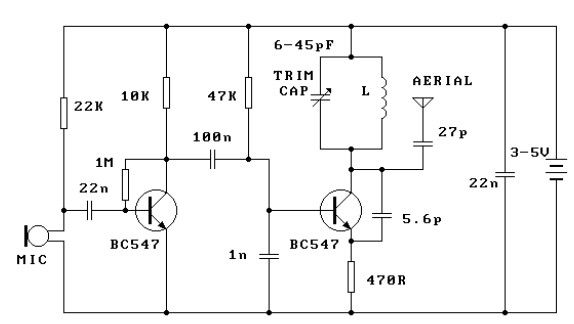
This FM transmitter circuit is very simple and has acceptable transmission. The signal transmitted from this FM transmitter circuit can be received at almost 300 meters in open air. The circuit requires a 3-volt operating voltage and can be...
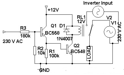
Three weeks ago, an inverter circuit diagram was introduced; however, the circuit did not include the AC to inverter switching part. Today, a 230 Volt AC to inverter switching circuit diagram is being presented. The circuit demonstrates inverter switching....
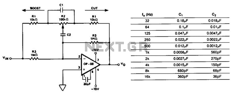
This circuit represents a section of an octave equalizer utilized in audio systems. The table outlines the values of C1 and C2 required to achieve specific center frequencies. This circuit can provide a boost or cut of 12 dB,...
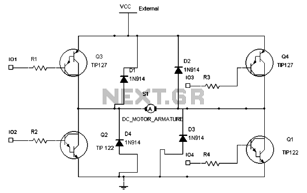
To maintain a constant speed of the motor under varying load conditions, a control application circuit is required. An H-Bridge circuit can be utilized to manage both the speed and direction of the motor. The accompanying diagram illustrates the...
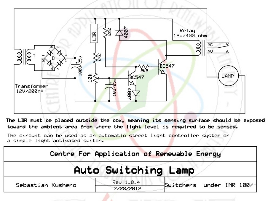
This sound-activated switch allows for sound control, which can be beneficial not only for robotic applications but also for home automation. The sound-activated switch operates by detecting specific sound frequencies or patterns, enabling the user to control various devices or...
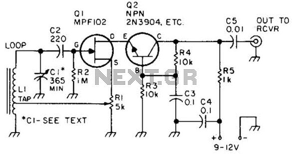
This preamplifier features a built-in regeneration control that enhances gain selectivity. CI represents a single or multi-gang AM broadcast-band tuning capacitor, while LI is a ferrite loop antenna tapped at approximately 15 to 25% of the total turns. This...
Warning: include(partials/cookie-banner.php): Failed to open stream: Permission denied in /var/www/html/nextgr/view-circuit.php on line 713
Warning: include(): Failed opening 'partials/cookie-banner.php' for inclusion (include_path='.:/usr/share/php') in /var/www/html/nextgr/view-circuit.php on line 713