
Norman P2000D Modeling Light Circuitry
The P2000D features dual independent modeling light circuits, each corresponding to its respective channel. This design allows for versatile lighting control without interference from the strobe circuitry, which operates at high voltage. Each modeling light circuit includes an On/Off switch, ensuring that users can operate the modeling lights independently of the strobe functionality, which is critical for troubleshooting and maintenance.
The top panel of the P2000D contains two potentiometers that allow for precise adjustment of the modeling light power levels. These potentiometers are connected to a dedicated circuit board located within the upper section of the device. This circuit board employs a TRIAC dimmer, which is a solid-state device known for its ability to control power flow and adjust the brightness of incandescent lamps. The TRIAC is controlled by the potentiometers, enabling smooth dimming of the modeling lights.
The output from the TRIAC dimmer is routed through a grey wire to Pin F on the strobe lamp connectors, while the return path for power is established via Pin E. This configuration ensures that the modeling lights receive the appropriate voltage and current levels for optimal performance. The schematic for the control board has been carefully traced to facilitate any necessary repairs in the future, although specific component values, such as the trim pot, were not documented.
As the project progressed, the acquisition of a Norman TriLite provided an opportunity to further explore the high voltage circuitry associated with the strobe operation. The absence of a transformer capable of stepping up the mains voltage indicates that a voltage multiplier is likely in use. A 3X voltage multiplier would provide the necessary voltage levels for strobe operation, as a 2X multiplier would fall short of the required specifications. This understanding of both the modeling light and strobe circuits is essential for effective troubleshooting and repair of the P2000D lighting system.There are two independent modeling light circuits for the P2000D - one for each of the two channels. The modeling light circuit is completely independent from the high voltage strobe circuitry - to the point of having its own On/Off switch. This means, of course, that just because the modeling lights are working your strobe circuits can be fried.
Be careful if someone sells you a pack and says - well I can`t test the strobe but the modeling lights are working. There are two modeling light power level potientiometers on the top panel. These lead to a small circuit board in the top half of the pack. This circuit board uses a fairly simple TRIAC dimmer to control the intensity of the lamps. The output from this board runs via a grey wire to Pin F on the strobe lamp connectors. Return power goes via pin E. I traced out the schematic of the control board as best I could. I did not attempt to measure the value of trim pot and could not identify the DIAC (though I pretty much am sure that it is a DIAC based on other dimmer schematics.
) I then sketched out the basic layout and circuit traces in case I needed to repair this circuit in the future. You can see it below (not entirely to scale ) A quick sidebar - When I started the project I had no strobe head.
However I just acquired a Norman TriLite (this is a projector lamp and strobe light in a spotlight type assembly) [more] So now that I warmed up with the modeling light circuit, it is time to start sketching out the high voltage circuitry use for the strobes. As I saw no transformer large enough to be used to step up the mains voltage, I knew that a voltage multiplier must be used.
A 2X multiplier would not produce enough voltage but a 3X mutliplier should. 🔗 External reference
Related Circuits
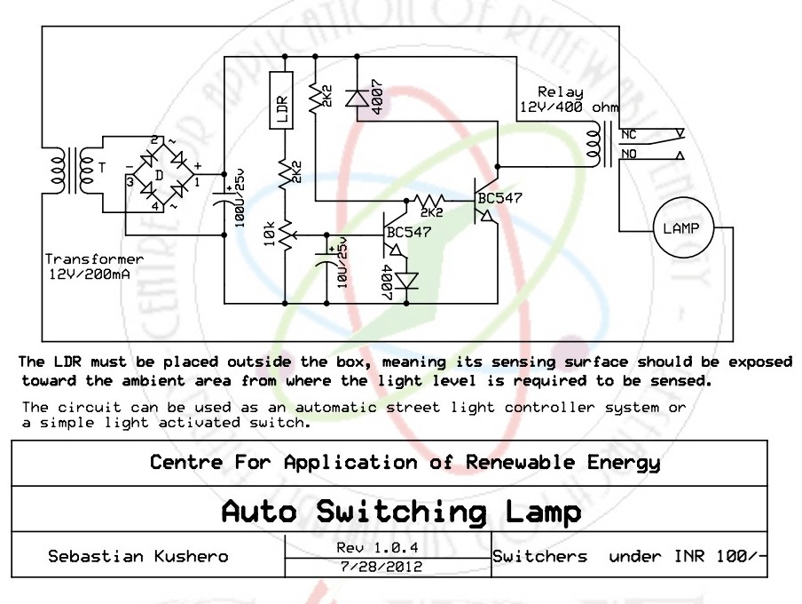
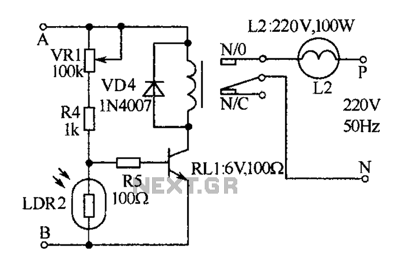
The light-activated switch circuit can be used for switching off a particular lamp or group of lamps in response to varying ambient light levels. The light-activated switch circuit utilizes a light-dependent resistor (LDR) as the primary sensing element to detect...
This circuit gradually switches the internal lights of a car on and off. The delay time can be adjusted by changing the values of the 10k and 4.7M resistors, as well as the capacitor. The circuit operates by utilizing a...
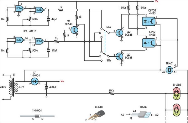
This circuit utilizes low-voltage AC to power a string of approximately 50 bi-color LEDs, with two LEDs connected in inverse parallel. The power supplied to the LEDs is managed by a Triac and two optocouplers, whose phototransistors are also...
The receiver, as depicted in the figure, assists patients in avoiding missed audio signals during the daytime. The receiver operates independently, and the lighting will automatically turn off. At night, the lighting signal receiver activates simultaneously with the patient's...
The circuit utilizes relay control. The voice switch operates as follows: upon the first clap, the load (lights) is activated; upon the second clap, the load (lights) is deactivated. This system can be employed to control lighting in residential...
The drawing below illustrates a multistage light sequencer using discrete components and no integrated circuits. The concept is not new; a similar circuit was developed approximately 40 years ago using germanium transistors. The design connects the lights so that...
Warning: include(partials/cookie-banner.php): Failed to open stream: Permission denied in /var/www/html/nextgr/view-circuit.php on line 713
Warning: include(): Failed opening 'partials/cookie-banner.php' for inclusion (include_path='.:/usr/share/php') in /var/www/html/nextgr/view-circuit.php on line 713