
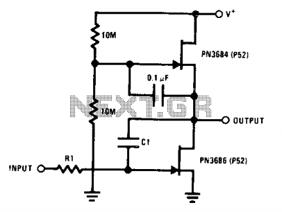
Jfet ac coupled integrator
The described circuit primarily focuses on utilizing operational amplifiers (µ-amps) to achieve significant voltage amplification. The integration of a Miller integrator or capacitance multiplier enhances the circuit's ability to handle extended time constants, making it suitable for applications requiring precise signal processing over longer durations.
In the schematic, the operational amplifier is configured in a feedback arrangement that allows for high gain. The input signal is fed into the non-inverting terminal, while the inverting terminal is connected to a feedback loop that includes both resistive and capacitive components. The configuration of these components is crucial as it determines the frequency response and stability of the circuit.
The Miller integrator function is achieved by introducing a capacitor in the feedback loop, which influences the phase response and gain characteristics of the circuit. The capacitor's value, in conjunction with the feedback resistor, defines the time constant of the circuit, allowing it to integrate the input signal over a specified duration. This is particularly useful in applications such as signal smoothing, filtering, and waveform generation.
Overall, the circuit's design emphasizes simplicity and effectiveness, leveraging the properties of operational amplifiers to produce a high-gain output while managing long time constants efficiently. Proper selection of component values is essential to optimize performance and ensure the desired response characteristics are achieved.This circuit utilizes the "µ-amp" technique to achieve very high voltage gain. Using CI in the circuit as a Miller integrator, or capacitance multiplier, allows this simple circuit to handle very long time constants. Here is the circuit. 🔗 External reference
Related Circuits
This flip-flop circuit is a free-running astable multivibrator, with the bases and collectors of both emitter-biased transistors directly coupled to each other. The switching action is facilitated by a capacitor in each emitter circuit. This configuration produces triangular waves...
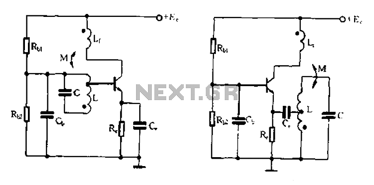
Base frequency selection, frequency-selective emitter type transformer coupled oscillator circuit The described circuit is a transformer-coupled oscillator that utilizes an emitter type configuration to achieve frequency selection. This type of oscillator is designed to generate signals at specific base frequencies,...
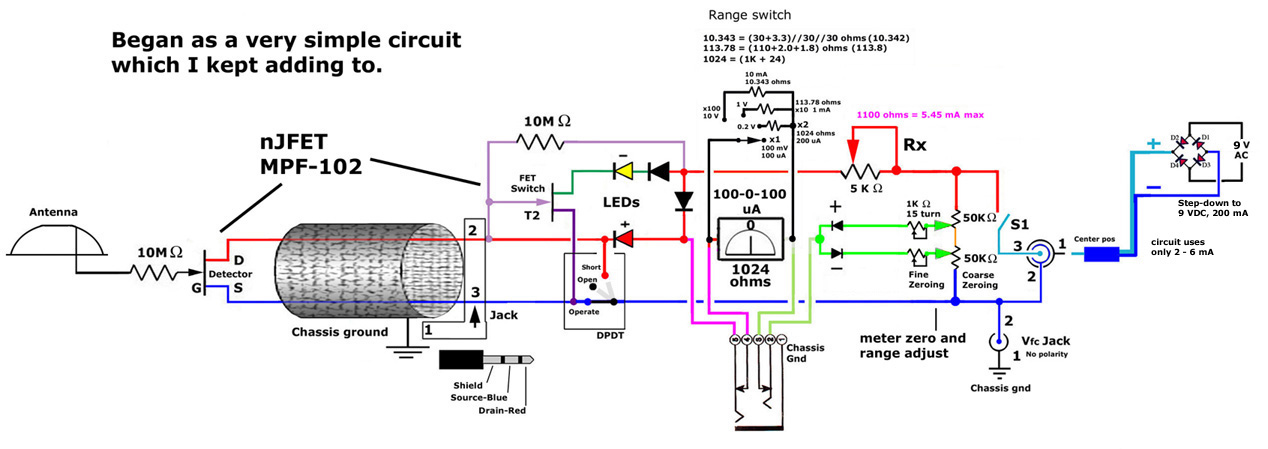
This post discusses the construction of multiple versions of JFET static charge detectors, highlighting observed differences that are not easily explained. The JFET (Junction Field Effect Transistor) static charge detector operates by utilizing the unique characteristics of JFETs to sense...
A Coil Coupled Operation Metal Detector made from readily obtainable components and using an ordinary medium receiver as a detector. The metal detector shown here may well represent a new genre. At any rate, after some exposure, it is...
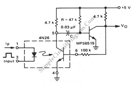
This is a pulse stretcher circuit utilizing an optocoupler. The circuit employs a 4N26 optocoupler in conjunction with a standard one-shot circuitry. The pulse stretcher circuit is designed to elongate the duration of an incoming pulse signal, which is particularly...
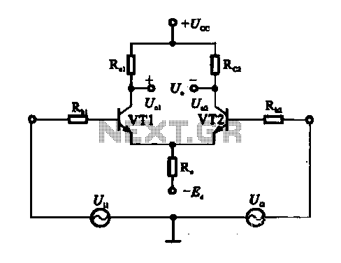
An emitter-coupled differential amplifier circuit is designed to suppress zero drift through circuit symmetry. The effectiveness of zero drift suppression improves with better symmetry; however, in practice, achieving complete symmetry is not feasible. Consequently, the basic differential amplifier circuit...