
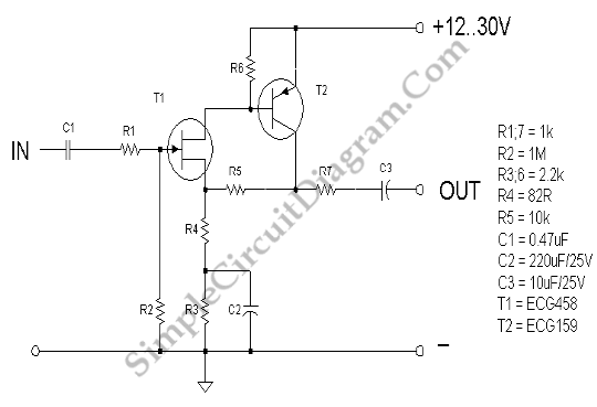
JFET AC Coupled Integrator
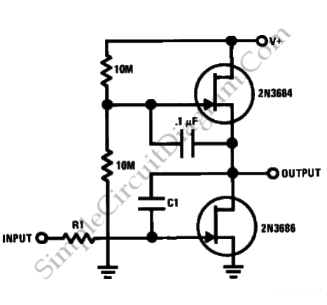
The JFET AC Coupled Integrator circuit is designed to provide significant voltage amplification while integrating input signals over time. The core component of this circuit is the Junction Field Effect Transistor (JFET), which is known for its high input impedance and low noise characteristics, making it ideal for sensitive applications.
The circuit typically consists of a JFET configured in an integrator topology, where the input signal is coupled through a capacitor to the gate of the JFET. This AC coupling allows the circuit to block any DC offset from the input signal, ensuring that only the AC components are processed. The capacitor also plays a critical role in defining the frequency response of the integrator, as it determines the time constant of the integration process.
The output of the JFET is taken from the drain, where a load resistor is connected. This resistor, in conjunction with the JFET's transconductance, sets the gain of the circuit. By adjusting the values of the load resistor and the input capacitor, the circuit can be tuned to achieve the desired voltage gain and frequency response.
Feedback can be implemented in the circuit to stabilize the gain and improve linearity. This is often done by connecting a resistor from the output back to the gate or source of the JFET. The use of feedback not only enhances the performance of the integrator but also helps in reducing distortion, making the circuit suitable for high-fidelity applications.
In summary, the JFET AC Coupled Integrator circuit is a powerful tool for achieving high voltage gain while integrating input signals, making it valuable in various electronic applications, including signal processing and analog computation.This is JFET AC Coupled Integrator circuit. This circuit is used to achieve very high voltage gain. To achieve very high voltage gain this circuit uses.. 🔗 External reference
Related Circuits
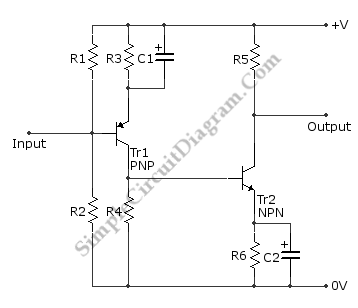
This is a directly coupled (DC) amplifier circuit. It is constructed using NPN and PNP transistors and is designed to amplify direct current (DC) signals. The directly coupled amplifier circuit utilizes both NPN and PNP transistors to achieve its amplification....
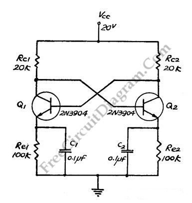
This flip-flop circuit functions as a free-running astable multivibrator, where the bases and collectors of both emitter-biased transistors are directly coupled. The switching action is facilitated by a capacitor in each emitter circuit, resulting in the generation of triangle...
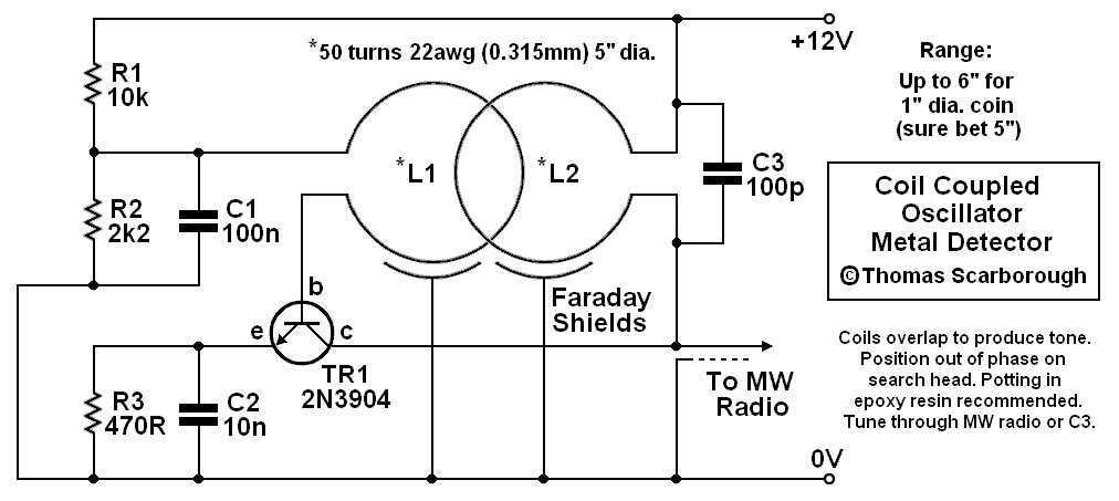
A Coil Coupled Operation Metal Detector made from readily obtainable components and using an ordinary medium receiver as a detector. The metal detector shown here may well represent a new genre. At any rate, after some exposure, it is...
Noise in an amplifier circuit is intrinsically generated by each component within the circuit. Resistors, capacitors, and semiconductors all contribute to noise generation. Noise in an amplifier circuit can significantly affect performance and signal integrity. Each component, including resistors, capacitors,...
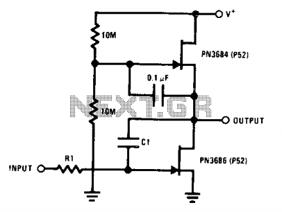
This circuit employs the "µ-amp" technique to achieve a very high voltage gain. By using a CI in the circuit as a Miller integrator or capacitance multiplier, this simple configuration can manage very long time constants. The described circuit primarily...
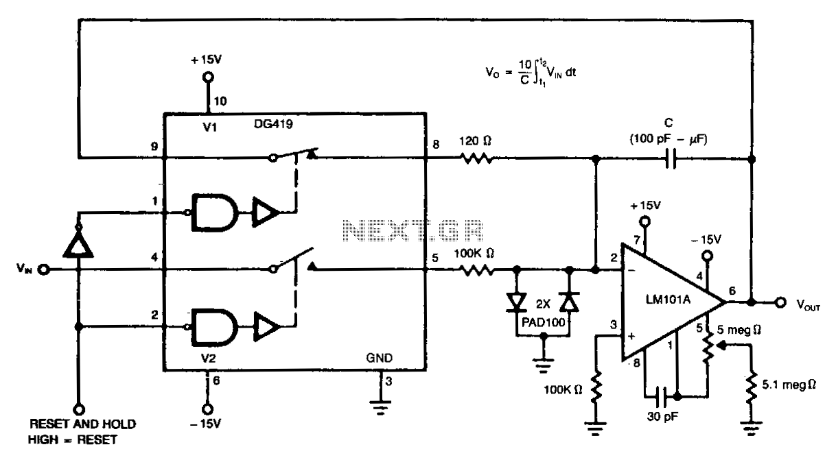
The low Rds and high peak current capability of the DG419 makes it ideal for discharging an integrator capacitor. A high logic input pulse disconnects the integrator from the analog input and discharges the capacitor. When the logic input...
Warning: include(partials/cookie-banner.php): Failed to open stream: Permission denied in /var/www/html/nextgr/view-circuit.php on line 713
Warning: include(): Failed opening 'partials/cookie-banner.php' for inclusion (include_path='.:/usr/share/php') in /var/www/html/nextgr/view-circuit.php on line 713