
JMP50 1987 preamp
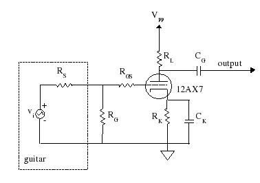
The Marshall JTM50 and JMP50 amplifiers are notable for their innovative preamp configurations that enhance tonal versatility and response. The use of a 12AX7 tube in place of a 12AY7 significantly boosts the voltage gain, making these amplifiers particularly suited for high-gain applications. The design choices, including the variations in cathode resistor values and bypass capacitors, allow for tailored frequency responses, particularly in managing bass attenuation in the bright channel. The output coupling capacitor values also play a crucial role in shaping the overall sound, where minor adjustments can lead to significant differences in tonal characteristics. The careful selection of resistor values in both the normal and bright channels ensures that each channel operates optimally, allowing for a wide range of tonal options that cater to different playing styles and preferences. The increase in output impedance in comparison to the Bassman circuit affects the gain transfer to subsequent stages, indicating a sophisticated understanding of signal flow and amplification dynamics within the design. Overall, the Marshall JTM50 and JMP50 exemplify a blend of classic design principles and modern adaptations that continue to influence guitar amplification technology.The Marshall JTM50 and JMP50 use two configurations for the first preamp. One is the same design as in Marshall`s Bluesbreaker and JTM45 and is identical to the Fender Bassman 5F6-A except for the tube: a high-mu 12AX7 instead of a medium-mu 12AY7. The 250uF cathode bypass capacitor CK is sometimes increased to 320uF or 330uF with very little impa ct on audio frequencies. In the plate circuits RL=100k and RK=820. For the high-gain inputs RG=1M and RGS=34k. For the low-gain inputs RG=RGS=68k. The output coupling capacitors are CG=0. 022uF versus 0. 02uF for the Bassman, which is an insignificant difference that resulted, most likely, from parts availability. Marshall`s substitution of a 12AX7 triode into the 5F6-A preamp circuit affects mostly the overall voltage gain.
Using our Preamp Output Impedance Calculator we get an unloaded voltage gain of 62 for the Plexi, versus only 35 for the 5F6-A. Not all of this increased gain shows up at the grid of the next tube, however, because the output impedance of the preamp rises to 38k, compared to only 20k for the Bassman.
The JMP50 plate load resistor is RL=100k. The cathode resistor RK is 820 ohms for the normal channel and 2. 7k for the bright channel. For the high-gain inputs RG=1M and RGS=34k. For the low-gain inputs RG=RGS=68k. The output coupling capacitor CG is 0. 022uF for the normal channel, but is reduced by a factor of 10 to only 0. 0022uF for the bright channel, increasing bass attenuation. Our Coupling Capacitor Caclulator shows attenuation of almost 3dB at 82 Hertz, which is the lowest note on a guitar with standard tuning. The cathode bypass capacitor CK is either 250uF or 320uF for the normal channel, which fully bypasses the cathode resistor for all audio frequencies.
It is only 0. 68uF for the bright channel, which bypasses the cathode resistor only at midrange and higher frequencies. At low frequencies the negative feedback from the cathode resistor reduces the gain. When driving a 1M load our Cathode Bypass Capacitor Caclulator shows a gain of 28 at 82Hz, rising to 59 at 1.
6kHz. For the 5F6A-style preamp the cathode resistor carries the DC current of both triodes. For the DC operating point this means that the effective resistance for one triode is 1. 64k, double the value of the resistor. With the two cathodes separated, however, Marshall leaves the cathode resistor for the JMP50 normal channel at 820 ohms. This raises the grid line, causing it to cross the load line at a much higher point. The net result is that the normal-channel triode operates closer to saturation and further from cutoff compared to the Bassman-style circuit.
In contrast, Marshall increases the bright channel cathode resistor in the JMP50 from an effective value of 1. 64k to a value of 2. 7k. In terms of DC plate current we can think of the Marshall JMP50 Model 1987 normal channel triode as operating "hotter" and its bright channel "colder" than in the Bassman-style circuit.
🔗 External reference
Related Circuits
JFET iPod preamplifier, DIY Hi-Fi, schematic The JFET iPod preamplifier circuit is designed to amplify the audio signal from an iPod or similar portable audio device, enabling it to drive higher impedance loads such as amplifiers or speakers. This circuit...

A general-purpose preamplifier/mixer accepts up to four inputs, has a gain of 1600, and provides bass and treble controls that can be varied ± 10 dB at 100 Hz and 10 kHz respectively. More: IC1 and IC2 = LM301A. This...
This is a simple low-impedance preamplifier circuit diagram used to amplify an audio signal. The circuit operates with a 12V DC power source and is straightforward due to its minimal component count. The low-impedance preamplifier circuit is designed to enhance...
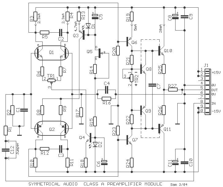
The preamplifier that appears in the figure is a completely symmetrical preamplifier, from the input as the exit and it works in Class A. It does not have somebody innovation, simply it uses good solutions, in order the result...
This is a clean preamp designed for use with a bass, a power amplifier, and a cabinet in a rehearsal space. The preamp is a unique design, developed from the ground up. The initial concept was an all-transistor design...
Tube amplifiers designed for headphones have the principal property that they can be used as preamplifiers too. In most cases, the output impedance of a tube headphone amplifier is (or should be) less than the output impedance of a...