
low impedance simple preamplifier

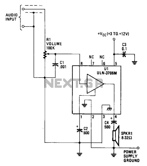
The low-impedance preamplifier circuit is designed to enhance weak audio signals, making it suitable for various audio applications, including microphones and musical instruments. The circuit typically employs an operational amplifier (op-amp) as the primary amplification component, which is characterized by its high input impedance and low output impedance. This configuration ensures that the audio signal is amplified without significant distortion or loss of quality.
The power supply for this circuit is provided by a 12V DC source, which is sufficient for most op-amps to function effectively while providing adequate headroom for audio signals. The simplicity of the circuit is a significant advantage, as it minimizes potential points of failure and reduces the overall cost of the design.
Key components in this preamplifier circuit may include resistors for setting gain, capacitors for coupling and decoupling signals, and possibly a potentiometer for adjustable gain. The layout of the circuit should be carefully considered to minimize noise and interference, particularly in audio applications where signal integrity is crucial.
Overall, this low-impedance preamplifier circuit is an efficient and effective solution for amplifying audio signals, making it a valuable tool in various electronic audio systems.This is a simple low impedance preamplifier circuit diagram. It used to amplify an audio signal. This circuit use a 12Vdc sources and very simple because work with less components. 🔗 External reference
Related Circuits
An H-bridge is commonly utilized for controlling DC motors and stepper motors. When managing a bipolar stepper motor, two complete H-bridges are required. Numerous H-bridge integrated circuits (ICs) such as the L298, MPC17529, and SN754410 (a quad half H-bridge)...
This article has two parts. Part I describes a way to determine the effective average impedance of a pair of mono headphones or a speaker using a device called a FILVORA. This is the optimum resistance with which to...
The input impedance of AC-coupled operational amplifier (op-amp) circuits is primarily determined by the resistance that establishes the DC operating point. When using CMOS op-amps, the input impedance is high, reaching up to 10 MΩ in current op-amps. For...
The 2N4416 JFET exhibits very low harmonic distortion, making it ideal for smooth oscillation in electronic circuits. It is particularly effective in applications where minimal harmonic content is essential for high-performance mixer circuits. Below is the circuit diagram of...
The amplifier functions with supply voltages up to 12 volts and can operate at lower voltages as low as 1.8 volts while maintaining acceptable distortion levels, albeit with reduced volume. Its power requirements make it suitable for applications powered...
This assembly is designed for amateurs who possess a collection of vinyl records and wish to convert them into a digital format on a personal computer. Alternatively, they may want to enjoy an old, cherished LP collection through their...