
jogging timer circuit diagram
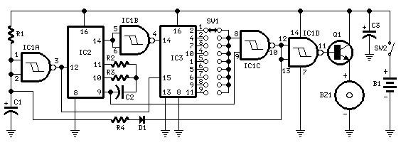
The circuit utilizes a rotary switch (SW1) to select the desired timing interval, allowing users to customize their beep notifications according to their jogging routines. The piezo sounder serves as the auditory alert, providing a clear and attention-grabbing signal. The timing mechanism is typically implemented using a combination of resistors, capacitors, and possibly a microcontroller or timer IC to accurately measure the time intervals.
In position 1, the timer circuit is configured to produce a short pulse every minute, which triggers the piezo sounder to emit three distinct beeps. The timing is achieved through a resistor-capacitor (RC) network that charges and discharges at a rate corresponding to one minute. As the switch is moved to subsequent positions, the values of the resistors or capacitors may be altered to extend the timing intervals appropriately.
For example, in position 2, the circuit is adjusted to create a two-minute delay before the sounder activates. This adjustment could involve increasing the capacitance or resistance in the timing circuit, thereby doubling the time it takes for the capacitor to charge to the threshold voltage required to activate the sounder. This method of extending the timer can be replicated for each position on the rotary switch, culminating in a maximum timing interval of nine minutes in position 9.
The design of this timer circuit is simple yet effective, making it suitable for a variety of applications beyond jogging, such as cooking timers, reminders, or any scenario where timed auditory notifications are beneficial. The use of a piezo sounder ensures low power consumption, making the circuit efficient for prolonged use, especially in portable applications. Overall, this timer circuit is a practical solution for users seeking a customizable timing mechanism with auditory feedback.This circuit was developed since a number of visitors of this website requested a timer capable of emitting a beep after one, two, three minutes and so on, for jogging purposes. As shown in the circuit diagram, SW1 is a 1 pole 9 ways Rotary Switch. Setting the switch in position 1, the Piezo sounder emits three short beeps every minute. In position 2 the same thing happens after a 2 minutes delay, and so on, reaching a maximum interval of 9 minutes in position 9..
🔗 External reference
Related Circuits
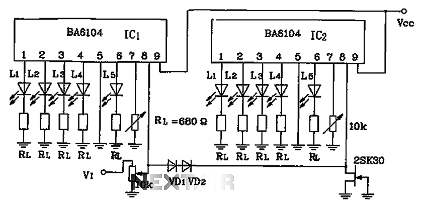
BA6104 is a five-digit LED level meter that functions as an LED display driver integrated circuit (IC). The configuration of the circuit is illustrated in the accompanying figure. The circuit utilizes a 10 by two-dot LED level display. The...
Over 1400 top electronics projects and electronic circuits with photos, datasheets, and easy-to-read schematics, along with explanations of how they work and how to build them. The collection comprises a vast array of electronics projects suitable for enthusiasts and professionals...
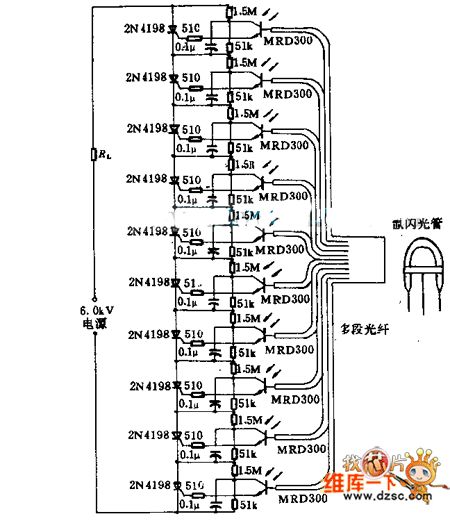
Light emitted by a Xenon flash tube is transmitted to the phototransistor MRD300 through an optical fiber. The sensitive current is amplified to trigger a series of thyristors simultaneously. Consequently, a high voltage of 6000V is applied to loader...

This circuit design generates a stable 1 kHz sine wave using an inverted Wien bridge configuration with components C1-R3 and C2-R4. It offers a variable output, low distortion, and low output impedance to ensure good overload capability. The circuit...
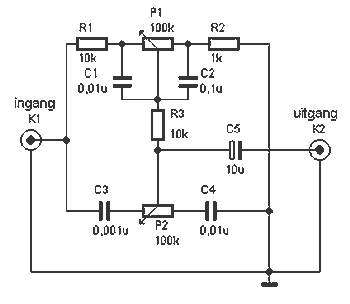
Here a simple design for an attractive tone. They operate on a passive principle, ie without amplification. The circuit only weakened and therefore require no power. As can be seen, the circuit is built with two T-filters in the...
This wireless headphones transmitter ensures quality reception over a distance of 2 meters. The oscillator frequency ranges from 1750 kHz to 3500 kHz, and for the antenna, it... The wireless headphones transmitter operates within a frequency range of 1750 kHz...
Warning: include(partials/cookie-banner.php): Failed to open stream: Permission denied in /var/www/html/nextgr/view-circuit.php on line 713
Warning: include(): Failed opening 'partials/cookie-banner.php' for inclusion (include_path='.:/usr/share/php') in /var/www/html/nextgr/view-circuit.php on line 713