
Joule Ringer 3
Warning: Undefined array key "extension" in /var/www/html/nextgr/view-circuit.php on line 468
Deprecated: strtolower(): Passing null to parameter #1 ($string) of type string is deprecated in /var/www/html/nextgr/view-circuit.php on line 468

The circuit described utilizes a compact design to achieve high efficiency in lighting applications. The 14-watt equivalent CFL bulb operates with minimal power input, demonstrating the effectiveness of the circuit in energy conservation. The use of a solar-charged battery provides versatility in energy sources, allowing for operation even under low charge conditions. Proper orientation and connection of the transistor are critical to prevent circuit failure, highlighting the importance of precision in electronic assembly.
The behavior of the circuit under varying loads is noteworthy; the self-adjusting nature allows for adaptability in different operational scenarios. The experimentation with coil configurations and the potential to parallel transistors indicates a progressive approach to optimizing performance. The findings regarding the reverse biasing of transistors reveal insights into power management, ensuring reliability at lower voltage levels.
The choice of wire gauge impacts thermal performance and efficiency, with the 30 AWG wire proving advantageous for LED applications. The results from the LED configurations suggest that series connections offer better performance compared to parallel setups, emphasizing the need for careful consideration of circuit design in achieving desired outcomes.
The integration of a wall transformer with a specific voltage rating offers a practical solution for powering the circuit, ensuring consistent performance for intended lighting applications. The option to switch to a 12-volt battery reinforces the circuit's versatility, making it suitable for various environments. Overall, the circuit represents a sophisticated blend of innovation and practical engineering, aimed at enhancing lighting solutions while minimizing energy consumption.14 watt equivalent light with just 1. 2 watts input. No, the light will be brighter and brighter as you approach the watt rating of the CFL bulb. What`s remarkable is that this circuit can light this CFL at very low voltage or higher too. A dimmable CFL is hard to do usually. Lets say you run a solar charged battery and the battery is run down a bit. The light will still come on. Try that with an ordinary 12/120 volt inverter! p. s. - take your time and really make sure the transistor is oriented correctly. and that all other wires are placed correctly. You may want to mark on some paper around the transistor what goes where. Its so easy to get something backwards and you`ll blow the transistor, or it wont work. Once you get it working notice the effect of your hand near the coil near the top vs bottom. Hold an LED by one end and notice where it lights. Try some AV plugs with LED or another CFL. Fun, fun, fun ! As long as the primary goes end to end on the secondary I don`t notice any tuning at all, or much difference how many turns the primary is. That may affect volts vs amps though. Yes, volts x amps = watts Interesting thing about reverse biasing a transistor - power is 2-3 times less than rated max so you wont ever burn them up on 12 volts.
That is what I am seeing with my little 2N2222 which can handle 680 ma. I am seeing 200-225 ma. I don`t know if it is possible but I will try paralleling two primary coils, two transistors on the one secondary. I don`t know if they will synchronize or if the bias voltage/current will be split and result in the same power output anyway, but I have the room on the coil for another primary, and I can just plug in another transistor.
LaserSaber used two primaries on his Super Joule ringer and left one unconnected. LaserSaber also notes that the circuit self adjusts to load so maybe the transistors in parallel will both be biased equally and double power output for more load. Or maybe this is totally unnecessary. I very much look forward to the DIY. I had very little time last night to rework my replication, but what I tried did not work. Not happy with the wire I am using for L1, and will go purchase some new wire. My local home improvement stores only carry 20 guage bell wire and RS has 22 guage hook-up wire. Any preference on these two choices. Please post the link to your DIY when completed. Hi folks, I have not had much luck yet either with lynxsteams air coil lamp, though I did get a 13 watt gutted cfl to light up partially, think I have to make some changes to my primary-transistor combo, or use a smaller coil tower, less turns.
Then I hooked 30 leds up to the secondary output and fried a few of the leds before disconnecting, way too much voltage for the leds in series, so I unwound many layers of 30 awg and it is brightly lighting 21 leds in series. Just to add, Before I wound the 30 gauge secondary, I used a 4 turn secondary of plastic insulated 18 gauge wire for powering leds in parallel and the resistance of that wire caused excessive heating of TIP42C transistor.
Though the 30 awg secondary powering leds in series seems to be the most efficient way to go, providing brighter leds for less input and less stress on the transistor. Right now, I am using a wall transformer, rated 9 volts, 400 milliamps, which gives around 11. 7 volts no load, which runs the leds pretty well, since I intend to use this as a bathroom light or hallway light, full time usage, with the idea in mind of quickly being able to switch to 12 volt battery if needed.
By request, here is a video of "How to make the SJR2. 0" I made some mods but followed the basic idea. You can see that you can "hotrod" the basic joule ringer with more turns, you can use a tip2N3055, use magnet wire, skip the extra primary. The LEDs light brightly off a 9 volt, or super bright off 12 volts. I think a 11:1 ratio is necessary to get the vol 🔗 External reference
Related Circuits
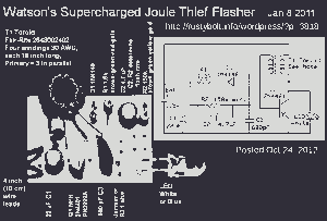
This picture and schematic were intended for posting on my Watson's blog, but it did not get published. The circuit schematic in question likely includes various electronic components arranged to perform a specific function. Typically, such schematics are used to...
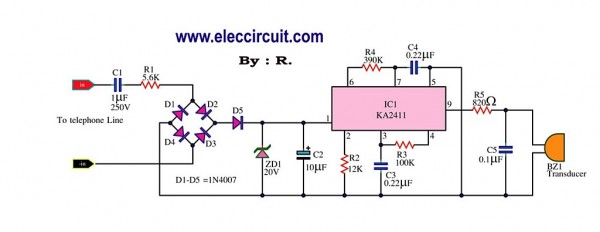
This circuit is designed to generate a loud ringing tone for an electricity bell in older telephone systems. It serves as a replacement for the original ringer that may be lost, eliminating the need for a new phone. The...
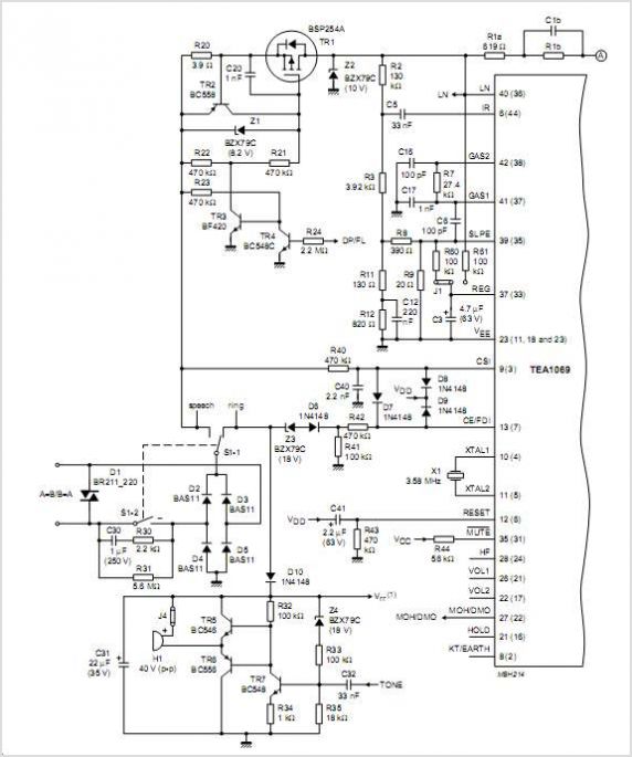
The TEA5711 is a high-performance Bimos integrated circuit designed for use in AM/FM stereo radios. It integrates all necessary functions, including the AM and FM front-end, AM detector, and FM stereo output stages. The TEA5711 is engineered to provide a...
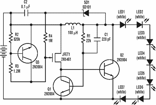
A low power, long-life LED flashlight circuit. Electronic Design proposed a simple circuit to resolve this in a recent article. The front end of their circuit draws less than a milliamp of extra current. The described LED flashlight circuit is...
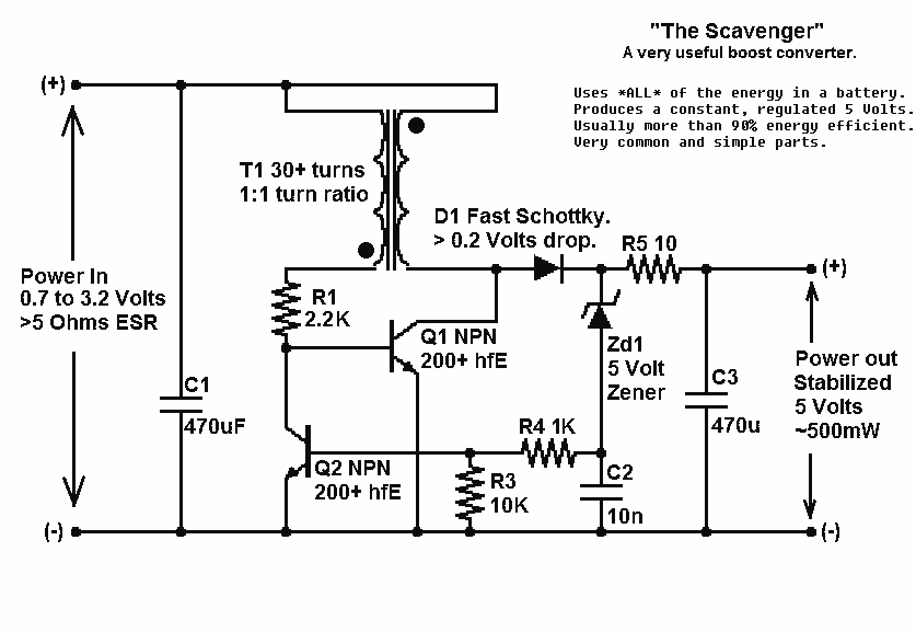
Presented here is a significant advancement in the design of simple, cost-effective, and efficient boost converters. To achieve an effective design, it is essential to convert current to voltage as efficiently as possible. This circuit excels in this regard. The...
This circuit generates a ringing sound similar to that produced by modern telephones. It comprises three nearly identical oscillators connected in a series configuration, each generating a square wave signal. The frequency of each oscillator is determined by the...