
loud ringer for phone using ka2411
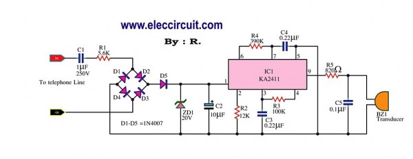
The ringing tone circuit operates by utilizing a simple yet effective design that integrates essential components to achieve its function. The circuit begins with the detection of the ringing signal from the telephone line, where the capacitors C1 and C2 play a crucial role. These capacitors couple the alternating current (AC) voltage signals from the telephone line to the rectifying diodes D1 and D2. D1 is responsible for detecting the positive half of the signal, while D2 detects the negative half, effectively allowing the circuit to process both polarities of the incoming ringing signal.
Upon detection, the voltage is reduced to approximately 10V, which is suitable for further processing within the circuit. The reduced voltage is then used to power the visual indicators—four light-emitting diodes (LEDs)—which flash in response to the frequency of the ringing tone. The typical frequency of the ringing tone is around 20 Hz, which corresponds to the standard ringing frequency used in telephone systems. This flashing provides a visual cue to the user, indicating that there is an incoming call.
In addition to the visual indication, the circuit also incorporates a piezo speaker, which generates an audible beep that corresponds to the ringing tone frequency. This dual indication system—both visual and auditory—ensures that the user is alerted to incoming calls effectively. The combination of the LEDs and the piezo speaker enhances the usability of the circuit, making it suitable for various applications where a loud ringing tone is necessary.
Overall, this loud ringing tone circuit is a practical solution for replacing lost telephone ringers, providing reliable performance and clear indicators for incoming calls without the need for a complete phone replacement. The straightforward design and quality components make it an excellent choice for retrofitting older telephone systems.This phone is loud ringing tone circuit for generating the electricity bell in the old telephone. This circuit is relatively loud. so can use to replacement the same ringer or the original telephone may be lost. We do not need a new phone. The detect ringing signal tone circuit with light and sound. It is easy to use and good quality, Do not enter the power supply. Which as Detect ringing signal tone circuit Or ring tones on the telephone line, a signal incoming calls. When an incoming call, When an incoming call, The C1, C2, will act as a coupling signal AC Volt to diodes D1, D2.
Signal voltage is reduced down to approximately 10V. By D2 to detect, only a negative signal, One extreme to the other end of the wire loop. The D1 detect a positive signal, and the 4 LED. Flashing light attached to it, with frequency of the ringging tone. Which is about 20 Hz. and piezo speaker, show the audio beep. beep, followed by a tone frequency of the ringing. 🔗 External reference
Related Circuits
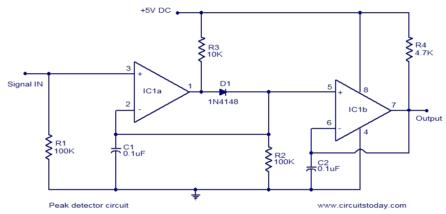
LM339-based peak detector circuit. Simple and easy to construct. Operates from a 5V DC single supply. LM339 is a dual comparator. The LM339-based peak detector circuit is designed to capture and hold the peak value of an input signal. This...
Circuit stereo TDA2822 audio power amplifier circuit schematics. In this series, the TDA2822M IC is utilized as the primary amplifier. Additionally, alternatives such as KA2209 and NJM2073 can also be employed. The TDA2822 audio power amplifier circuit is designed to...

PICLink RS232 low-cost development controller with ADC. The PICLink RS232 embedded controller module provides any microcontroller with RS232 communication capabilities. The PICLink RS232 embedded controller is designed to facilitate communication between microcontrollers and RS232 devices, making it an essential component...
With this circuit can determine whether any of the phones of the same line is busy (it's up the handset), with the help of a LED. The circuit has no measurable effect on the telephone, so that there are...
This is a simple microphone preamplifier circuit which you can use between your dynamic microphone and any equipment designed to work with an electret microphone (2 wire connection to electret capsule). This amplifier amplifies the low level signal to...
This is a DC power supply circuit designed to regulate 9 volts and provide a current output ranging from 1 amp to 2 amps. The circuit utilizes a modified TIP31 transistor, although alternative transistors such as TIP41, MJE3055, or...