
joule thief
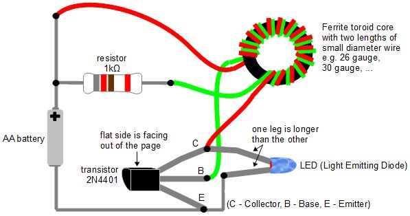
The Joule Thief circuit operates on the principle of a self-oscillating boost converter, which is particularly effective in extracting energy from low-voltage batteries. The core component, a transistor, functions as a switch that rapidly turns on and off, creating a magnetic field in the toroidal core. When the magnetic field collapses, it induces a voltage in the secondary winding, boosting the output voltage to a usable level. The circuit typically consists of a few essential components: a transistor, a resistor, a toroidal ferrite core, and two coils of wire wound around the core.
To construct the circuit, the first step involves winding the wire around the toroidal core. The primary coil is connected to the collector of the transistor, while the secondary coil connects to the base through a resistor. This configuration allows feedback to the base, enabling the transistor to oscillate. The choice of resistor value influences the frequency of oscillation, thereby affecting the output voltage and power delivered to the load. In practice, experimenting with different resistor values can help achieve the desired brightness for the LED or CFL.
The LED or CFL is connected to the output of the circuit, which is where the boosted voltage is delivered. It is crucial to ensure that the CFL used has its internal electronics removed, allowing it to be powered directly by the Joule Thief circuit. This setup demonstrates the ability of the Joule Thief to efficiently utilize energy from batteries that would otherwise be discarded, showcasing its potential for sustainable energy solutions and DIY electronics projects.The joule thief is an electronic circuit that allows you to make use of batteries normally considered dead. A battery is often considered "dead" when it can`t power a particular device. But what`s really happening is that the battery voltage is no longer high enough for the device when it`s used directly.
The joule thief circuit massages the volta ge and current coming from the battery so that the voltage is high enough, for periods of time, for the device to work continuously. The LED in the above photo requires 1. 85 volts but as the photo below shows, the battery voltage is only 1. 27 volts. When run through the joule thief circuit, the voltage is as high as 24 volts, as shown in the oscilloscope output n the photo on the right.
Notice that the LED is not always getting power, but it`s often enough to keep it lit. People, including myself, have gotten it to run a compact fluorescent lightbulb (CFL) by adding an extra coil of wire to the toroid core. Also, the electronics has to be removed from the CFL so that the joule thief circuit is powering the fluorescent tubes directly.
i. e. it must be a gutted CFL. Transistor - The legs of the transistor can be determined by noticing that there`s a flat side to the transistor case. See the diagram above. A large number of transistors have been reported to work: 2N4401, NET123AP, BC547B, 2SC2500, BC337, PN2222, to name just a few.
Resistor - The diagram says use a 1 kilo ohm resistor but I`ve used an 820 ohm one just fine. I`ve also seen a 2 kilo ohm one in use. Use whatever works for you. You can also use a potentiometer (a variable resistor) so that you can easily adjust it to select the resistance that gives the best light. Toroid ferrite core - Some people have gotten these by opening up compact fluorescent lightbulbs (CFLs).
I took mine out of some device whose original function I don`t know. To get it working, my first one had just 13 turns for each wire and I used a 30 gauge wire and a 26 gauge wire. The wire must be insulated. A variety of number of turns will work. This is something you can play with. Look at the diagram carefully to determine where the wires connect to. 🔗 External reference
Related Circuits
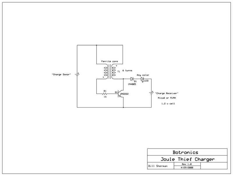
Allow a dead battery to energize another! An open circuit Joule Thief can generate 50 volts or more, sufficient to charge a AA or AAA NiCad or NiMH rechargeable battery. The Joule Thief is a minimalist circuit designed to extract...
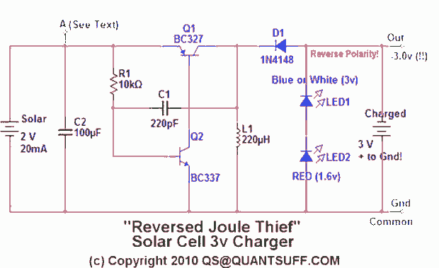
This design presents an innovative approach to the Joule Thief (JT) circuit typically utilized in garden lights. Instead of directly charging a 1.2V battery from the solar cell and converting the power to operate a 3-volt LED, this circuit...

Joule thief circuit along with videos, circuit diagrams, and explanations. The Joule thief circuit is a minimalist boost converter designed to extract energy from low-voltage sources, such as depleted batteries. This circuit is particularly effective for powering small electronic...
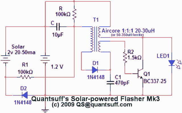
This circuit is a single transistor flyback (Joule Thief) circuit that features a third coil. With it, flash duration and brightness are significantly enhanced. The single transistor flyback circuit, commonly known as a Joule Thief, is designed to efficiently convert...
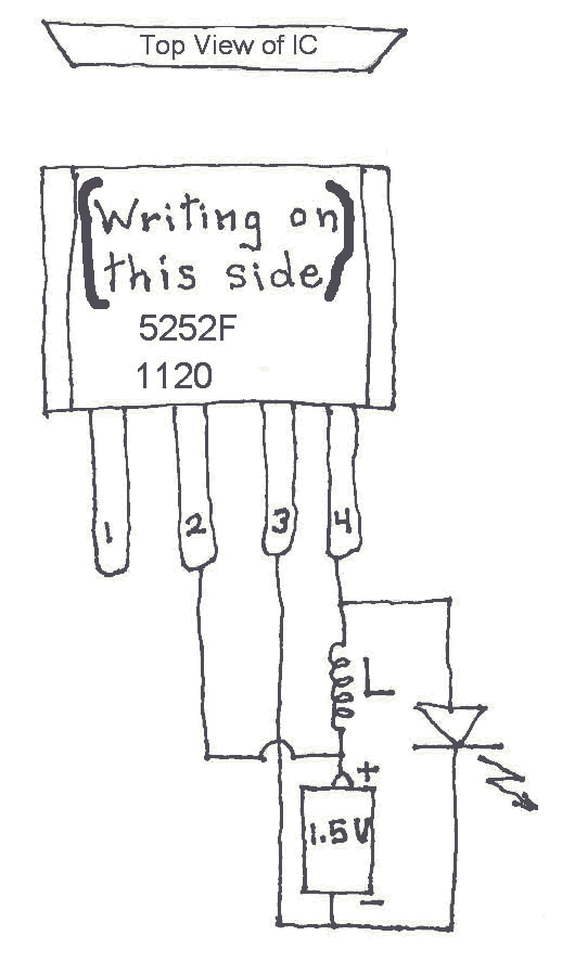
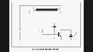
Many Joule Thief circuits traditionally rely on a bulky toroidal inductor that requires careful winding with copper wire. However, there are now compact 4-legged integrated circuits (ICs) available that can perform the same function using only a simple inductor,...
A compact Joule Thief circuit utilizes nine white LEDs, drawing approximately 250 mA at an input voltage of 1.5 V. During the video demonstration, the battery voltage was slightly below 1.3 V. The Joule Thief circuit is a simple yet...