
Modern Joule Thief Circuits
The Joule Thief circuit is a minimalist power converter that efficiently boosts the voltage from a single-cell battery (typically 1.5V) to a level sufficient to illuminate an LED, often around 3V to 3.5V. The primary components of this circuit include the compact 4-legged IC, a small inductor, a diode, and a capacitor, along with the battery and LED.
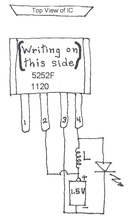
The 4-legged IC serves as the control unit, managing the switching of current through the inductor. This switching action generates a magnetic field in the inductor, which, when interrupted, induces a voltage spike that is rectified by the diode to power the LED. The inductor's physical size has been minimized without sacrificing performance, allowing for a more compact design that is ideal for applications where space is a constraint, such as in solar-powered devices.
In practical applications, the circuit can be assembled on a breadboard to facilitate prototyping and testing. The simplicity of the layout typically involves connecting the battery to the input of the IC, with the output connected to the LED through the diode. The inductor is connected in series with the IC, allowing it to perform its function of energy storage and voltage boosting.
The use of a small inductor, which may appear similar to a resistor, is crucial in maintaining the efficiency of the circuit. The inductor needs to be selected based on its inductance value, which affects the switching frequency and overall performance of the Joule Thief circuit.
This modern approach to Joule Thief design not only simplifies the construction process but also enhances the reliability and portability of low-power electronic devices, making it a valuable innovation in the field of electronics. The integration of these components into a single compact package opens up new possibilities for energy-efficient applications in portable and renewable energy systems.It seems that many Joule Thief circuits depend on a clunky (bulky and heavy) toroid or donut that has to be carefully wound with copper wire. But now there are several very small 4 legged ICs available that do the job using only a simple inductor, single cell battery and a LED. In effect, the 4 legged IC replaces the clunky toroid. I came across these ICs when I disassembled some solar powered yard lights. I looked for a toroid but only found a four legged IC and a part that looked like a resistor but actually was a very physically small inductor (coil). Both of these parts along with wire attachment points were soldered to a small circuit board. I was able to remove parts, attach wires to them and assemble them on a Radio Shack type of Breadboard to test and better understand this circuit.
🔗 External reference
Related Circuits

This article discusses several opamp-based headphone amplifier circuits, including suggestions for selecting opamps, input coupling and filtering, high current output stages and power supply options. There are no recommendations for specific opamp brands or models. For tube devotees, there...

Joule thief circuit along with videos, circuit diagrams, and explanations. The Joule thief circuit is a minimalist boost converter designed to extract energy from low-voltage sources, such as depleted batteries. This circuit is particularly effective for powering small electronic...
Class D amplifiers are significantly more efficient than traditional amplifiers; however, this high efficiency is accompanied by increased noise and distortion. The frequency and time-domain characteristics of a Class D amplifier, including its output filter, can be evaluated using...
The following circuit illustrates a VHF pre-amplifier circuit diagram. This circuit utilizes the BFS17 transistor. Features: designed for VHF applications. The VHF pre-amplifier circuit is essential for enhancing weak radio frequency signals in the VHF (Very High Frequency) range, typically...
The core of the circuit is a two-transistor flasher with frequency modulation applied to the base of the first transistor. When the pushbutton is pressed, the oscillation frequency increases to a peak, and upon release, the frequency decreases due...
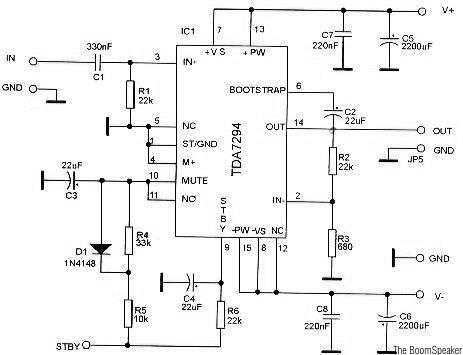
The TDA7294 is a monolithic integrated circuit housed in a Multiwatt15 package, designed to deliver high output power of up to 100W. It is intended for use as an audio Class AB amplifier in high-fidelity applications. The TDA7294 is a...
Warning: include(partials/cookie-banner.php): Failed to open stream: Permission denied in /var/www/html/nextgr/view-circuit.php on line 713
Warning: include(): Failed opening 'partials/cookie-banner.php' for inclusion (include_path='.:/usr/share/php') in /var/www/html/nextgr/view-circuit.php on line 713