
Super Joule Thief

The Joule Thief circuit is a simple yet effective boost converter designed to maximize the energy extracted from low-voltage batteries, such as AA or AAA cells. The circuit typically employs a single transistor, a transformer (often a bifilar-wound inductor), and a few passive components.
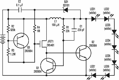
In this specific configuration, the circuit is optimized to power nine white LEDs, which collectively require a significant current of around 250 mA. This current draw indicates that the circuit must efficiently step up the battery voltage from a nominal 1.5 V to a higher operating voltage suitable for the LEDs, which often require around 3.0 V to 3.5 V for proper illumination.
The operation begins when the transistor is turned on, allowing current to flow through the primary winding of the transformer. As the current builds, it generates a magnetic field in the core. When the transistor switches off, the collapsing magnetic field induces a voltage in the secondary winding, which is then fed back to the base of the transistor, keeping it in an oscillating state. This feedback mechanism allows the circuit to continuously draw energy from the battery, effectively boosting the voltage to power the LEDs.
The choice of components, such as the transistor type (usually a small-signal NPN like the 2N3904), the inductor specifications, and the LED characteristics, must be carefully considered to ensure optimal performance. Additionally, the circuit may incorporate a resistor in series with the LEDs to limit the current and prevent damage while ensuring adequate brightness.
Overall, this Joule Thief configuration demonstrates a practical application of low-power electronics, enabling the use of nearly depleted batteries to power multiple LEDs, thus enhancing energy efficiency and sustainability in electronic designs.Small Joule Thief With 9 white LED draw about 250 mA at 1.5V the battery was a little under 1.3 Volt at the video time. 🔗 External reference
Related Circuits
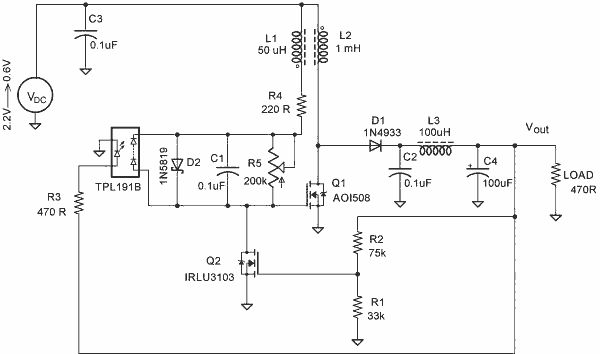
A simple blocking oscillator circuit can be utilized to increase voltage by leveraging the properties of coil inductance (V = L di/dt). Such a circuit is illustrated in Figure 1. The blocking oscillator circuit is a type of oscillator that...
The circuit utilizes two white LEDs, with the second LED connected across the emitter of the transistor and the negative ground. It requires its own limiting resistor in series, similar to R15 and D3 in the circuit diagram. If...
A low power, long-life LED flashlight circuit. Electronic Design proposed a simple circuit to resolve this in a recent article. The front end of their circuit draws less than a milliamp of extra current. The described LED flashlight circuit is...
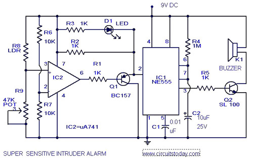
The circuit diagram illustrates an ultra-sensitive intruder alarm. The mere shadow of an intruder passing within a few meters of the circuit is sufficient to activate the alarm. In this setup, the IC2 uA741 is configured as a sensitive...
This is a simple RF receiver mainly for low-distance digital radio receiver application. The analog output of this circuit should be connected to a schmitt-trigger signal conditioning circuit with a proper value capacitor (from collector of T3). L1 for...

A 14-watt equivalent light operates with only 1.2 watts of input. The brightness of the light increases as it approaches the watt rating of the CFL bulb. This circuit can power the CFL at low or high voltages. A...