
joule thief schematic
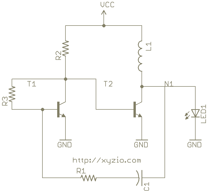
A Joule Thief is a minimalist circuit designed to extract energy from low-voltage sources, such as depleted batteries, and boost the voltage to a usable level. The core components of a Joule Thief include a transistor (T1), a resistor (R2), a feedback resistor (R3), and a transformer or inductor.
In operation, when the circuit is powered, current flows through R2, which is connected to the base of the transistor T1. This base current turns on T1, allowing a larger current to flow from the collector to the emitter. As T1 conducts, the magnetic field in the transformer or inductor builds up. The feedback resistor R3 is crucial as it senses the voltage across the inductor and feeds it back to the base of the transistor, creating a positive feedback loop that further enhances T1's conduction.
Once the magnetic field reaches a certain threshold, the transistor T1 turns off, causing the magnetic field to collapse. This rapid change induces a voltage spike in the opposite direction across the inductor. The voltage spike can be significantly higher than the original supply voltage, allowing the circuit to power devices that require a higher voltage than the source can provide.
The cycle then repeats: as the voltage across R2 drops, T1 turns back on, and the process continues. This oscillation allows the Joule Thief to effectively utilize the remaining energy in a low-voltage battery, making it an efficient solution for powering low-power devices from nearly depleted power sources. The simplicity of the design and its ability to operate with minimal components make the Joule Thief an excellent example of efficient energy harvesting in electronics.How a Joule Thief Works. This increase and decrease across R3 switches T1 on and off. As T1 switches on and off and the voltage across R2 varies. This voltage change at the base of 🔗 External reference
Related Circuits
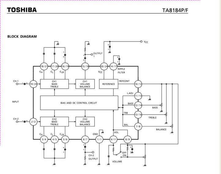
The TA8184P and TA8184F are DC-controlled integrated circuits designed for dual volume, balance, and tone (bass and treble) control. These ICs are suitable for applications in car stereos, radio cassette players, music centers, and TV multiplex sound receivers, providing...
Craftsman Garage Door Opener Schematic and Installation Manuals. Sears Craftsman Garage Door Opener Parts. With 15 years in the business, Garage Door Openers Superstore is a leading provider. The schematic for the Craftsman Garage Door Opener provides a comprehensive overview...
This circuit is basically the same as the 10 channel LED sequencer with the addition of solid state relays to control the AC lamps. The relay shown in the diagram is a Radio Shack 3 amp unit (part no....
There are two primary methods to control the speed of a DC motor: by varying the supply voltage and through pulse width modulation (PWM). The first method is less convenient, particularly in digital systems, as it necessitates the use...
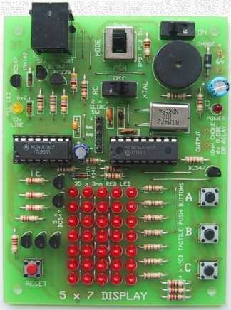
Your 5x7 display is my favourite toy; the tunes and graphics in the elevator display always impress my mates! Since building the display I developed my own 400 dot matrix using a pic and the SN74154 4bit binary to...
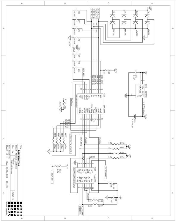
The following are detailed schematics for the QScreen Controller. The QScreen Controller integrates an embedded computer utilizing the 68HC11 microcontroller, along with a touch panel and an LCD (liquid crystal display) graphic user interface (GUI) that is well-suited for...
Warning: include(partials/cookie-banner.php): Failed to open stream: Permission denied in /var/www/html/nextgr/view-circuit.php on line 713
Warning: include(): Failed opening 'partials/cookie-banner.php' for inclusion (include_path='.:/usr/share/php') in /var/www/html/nextgr/view-circuit.php on line 713