
AC Lamp Chaser schematic
This circuit utilizes a 10-channel LED sequencer design enhanced with solid-state relays for controlling AC lamps. The primary component is the Radio Shack 3 amp solid-state relay (part no. 275-310), which requires a 1.2 volts DC signal for activation. The internal LED of the relay is presumed to draw a few milliamps, although no specific current rating is provided. To limit the current and ensure safe operation, a 360-ohm resistor is used, which restricts the current to approximately 17 mA when powered by a 9-volt supply.
In testing, a different solid-state relay was used, which operates at 3 volts and requires only 1.5 mA for activation. This relay is capable of handling voltages up to 30 volts DC and significantly greater currents, making it suitable for various applications.
The sequencer circuit can be expanded to include up to 10 channels by adding more relays and corresponding driver transistors. The heart of the sequencing is driven by a 4017 decade counter, which provides a method for controlling the sequence of the lamps. The reset line of the 4017 (pin 15) is connected to the fifth output (pin 10), allowing the sequence to progress from the first to the fourth lamp before resetting and repeating the cycle. For configurations requiring additional stages, the reset pin can be connected to a higher output count, enabling a longer sequence of operation. This flexibility allows for customization based on the specific application requirements.This circuit is basically the same as the 10 channel LED sequencer with the addition of solid state relays to control the AC lamps. The relay shown in the diagram is a Radio Shack 3 amp unit (part no. 275-310) that requires 1.2 volts DC to activate. No current spec was given but I assume it needs just a few milliamps to light the internal LED. A 360 ohm resistor is shown which would limit the current to 17 mA using a 9 volt supply. I tested the circuit using a solid state relay (of unknown type) which required only 1.5 mA at 3 volts but operates up to 30 volts DC and a much higher current.
The chaser circuit can be expanded up to 10 channels with additional relays and driver transistors. The 4017 decade counter reset line (pin 15) is connected to the fifth count (pin 10) so that the lamps sequence from 1 to 4 and then repeat. For additional stages the reset pin would be connected to a higher count. 🔗 External reference
Related Circuits
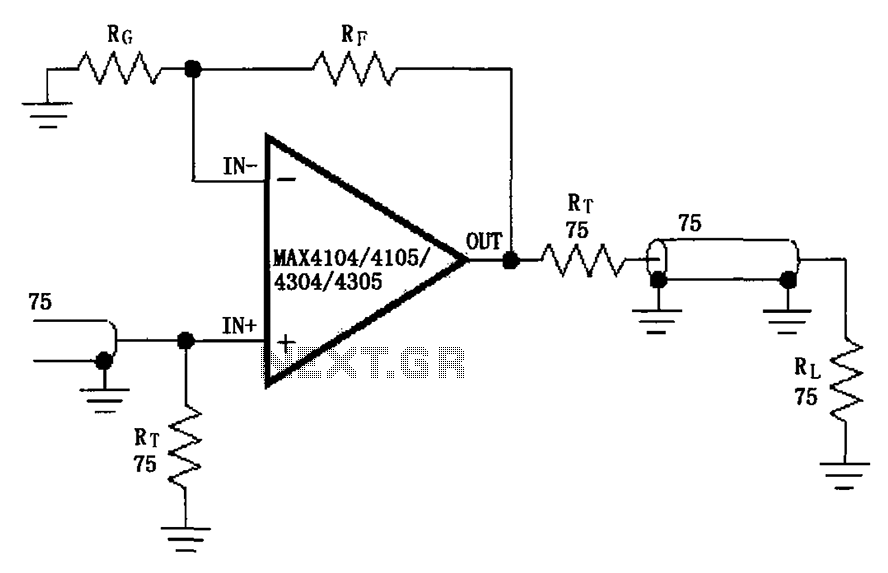
The circuit illustrated in the figure features a MAX4104/4105/4304/4305 video cable driver amplifier. This circuit is designed for use with coaxial transmission lines, optimizing the amplification of video signals to minimize reflections and maximize power transfer. The output impedance...
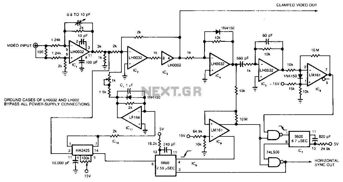
The circuit utilizes a track-and-hold amplifier in a closed-loop configuration to clamp the back-porch voltage of a standard video waveform to 0 V. The outputs of the circuit include a clamped composite video signal and a TTL-level horizontal blanking...
Continuous wave (CW) operation is achievable with a current of up to 350 mA from a supply voltage range of 2 to 6 V. The system supports TTL modulation frequencies of up to 10 kHz, with an adjustable duty...
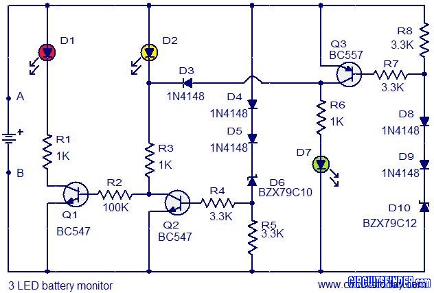
This is the circuit diagram of a 3 LED bar graph type battery monitor circuit that is ideal for monitoring the voltage level of an automobile battery. When battery voltage is 11.5V or less, transistor Q1 will be on...
For a candle to burn, we need a heat source (the flame of a match) and to extinguish it, you do it just to blow out. The following circuit behaves similarly. If you use your fingers heats the thermistor,...
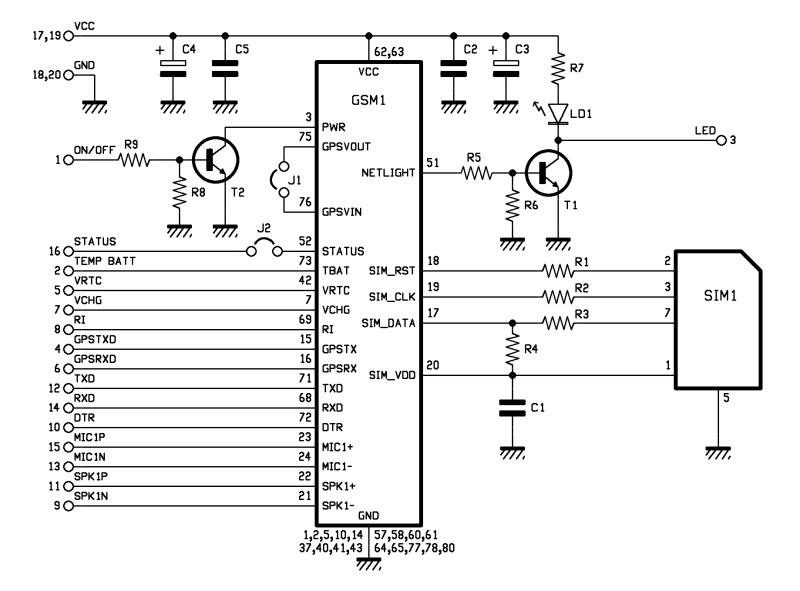
The roles of capacitors C1, C4, and C5 in a circuit may not be immediately clear. Capacitors on the power rail help to smooth out the signal by reducing current ripple, which can be observed using an oscilloscope. Resistors...