
1996 Suzuki Esteem Cooling Fan Circuit Diagram

The cooling fan system in the 1996 Suzuki Esteem is designed to maintain optimal engine temperature by regulating the operation of various fans. The system primarily consists of the following components:
1. **Control Relay**: This component acts as a switch to control the power supply to the radiator fan and other associated fan motors. When the engine temperature rises above a predetermined level, the engine control module (ECM) signals the control relay to activate the radiator fan.
2. **Radiator Fan Motor**: This motor is responsible for drawing air through the radiator to dissipate heat from the engine coolant. It operates at different speeds depending on the coolant temperature and the signals received from the ECM.
3. **Air Conditioning Fan Motor**: This motor operates in conjunction with the air conditioning system. When the air conditioning is activated, this fan helps to cool the condenser, ensuring efficient operation of the air conditioning system.
4. **Condenser Fan Motor**: Similar to the air conditioning fan motor, this component aids in cooling the refrigerant in the condenser, enhancing the overall efficiency of the vehicle's cooling system.
5. **Junction Box**: This box houses various electrical connections and serves as a central point for distributing power to different components of the cooling fan system.
6. **Fuse and Relay Box**: This box contains fuses and relays that protect the electrical circuits from overloads and control the operation of the fans based on the signals received from the ECM.
7. **Engine Control Module (ECM)**: The ECM monitors engine temperature and other parameters, controlling the operation of the cooling fan system to ensure the engine operates within its optimal temperature range.
The circuit and wiring diagrams for the 1996 Suzuki Esteem Cooling Fan system illustrate the interconnections between these components, providing a clear representation of the electrical pathways and control logic involved in the system's operation. Proper understanding of these diagrams is essential for troubleshooting and maintaining the cooling fan system effectively.The 1996 Suzuki Esteem Cooling Fan system consists of control relay for: radiator fan (located in relay box), air conditioning fan motor, radiator fan motor, condenser fan motor, junction box, fuse and relay box, engine control module. The following circuit diagram and wiring diagram / schematic shows 1996 Suzuki Esteem Cooling Fan system.
🔗 External reference
Related Circuits
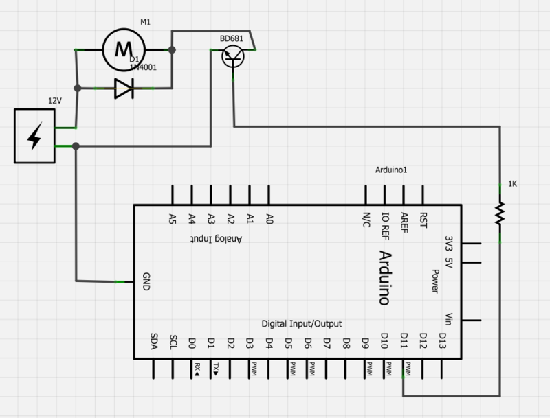
Power a 12V fan using a Darlington transistor to control the speed from an Arduino. When wired as described, nothing happens even though a PWM signal is being sent. It is suggested to edit the question and ensure the...
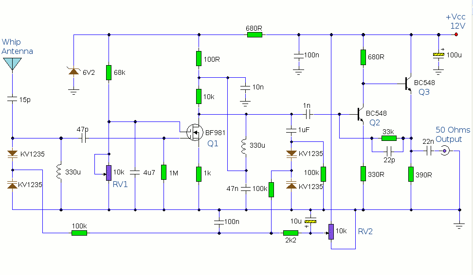
The antenna amplifier circuit comprises approximately 40 components, featuring two NPN transistors (BC548), one MOSFET (BF981), two varicap diodes (KV1235), and a 6.2V zener diode. It includes a 330µH inductor/coil, which can be modified for operation on different frequency...
Servo motors are utilized in various applications, including robotics, puppetry, photography, and more. These compact motors can adjust their output shaft to a specified position on command and maintain that position. Most servos offer a range of motion of...
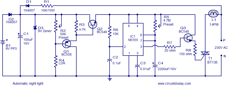
A simple and inexpensive automatic night light circuit designed using the timer IC NE555, which extinguishes after a preset time. This time can also be adjusted. The automatic night light circuit utilizes the NE555 timer IC configured in monostable mode....
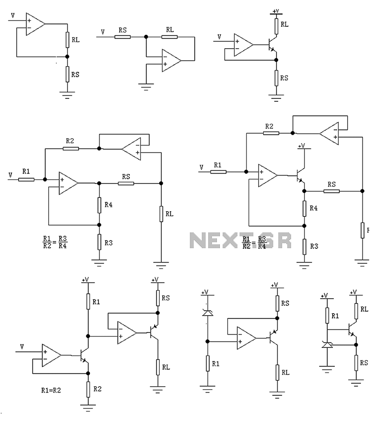
The circuit is designed to provide several constant current outputs to the load resistor RL. The first RL is floating and is rarely utilized. The second RL serves as a virtual ground and is not commonly used either. The...
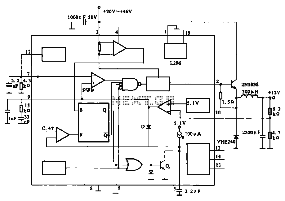
The circuit outputs 12V at 10A and utilizes a high-current switching power supply design based on the L296 component. This configuration allows for an output current of up to 10A, and the entire circuit is compact with minimal component...