
just sanity check transformers
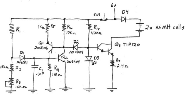
The design of the constant-current charger involves several critical components and considerations to ensure efficient operation and thermal management. The power supply selection is paramount; a transformer with a secondary output of approximately 6.3V at 2A is ideal, but the actual output under load conditions must be carefully calculated. The use of two separate CC transistors allows for independent control of each battery bank, enhancing the reliability and performance of the charging process.
The circuit should incorporate a precision voltage reference to ensure that the output voltage remains stable even with variations in load. This can be achieved through the use of a linear voltage regulator or a switching regulator, depending on the efficiency requirements. The CC transistors should be selected based on their thermal characteristics and current handling capabilities, ensuring that they can dissipate heat effectively without exceeding their maximum junction temperature.
Thermal management is a significant concern in this design. Heatsinks should be employed for the CC transistors to maintain their operating temperatures within safe limits. Additionally, the layout of the circuit should facilitate airflow around the components to further assist in cooling. The use of thermal paste between the transistors and heatsinks can enhance thermal conductivity.
The charging algorithm should include temperature monitoring via thermistors, which is already part of the design. Implementing a microcontroller could enable more sophisticated charging profiles, such as tapering the charge current as the battery approaches full charge or implementing safety features to prevent overcharging.
For the rectification stage, a full-wave bridge rectifier configuration is recommended to convert the AC voltage from the transformer to DC efficiently. Schottky diodes may be used for their low forward voltage drop, which minimizes power loss during the rectification process. Following rectification, a smoothing capacitor should be included to reduce voltage ripple and provide a stable DC output.
Finally, the design should include protection features such as fuse or circuit breaker to prevent damage in case of short circuits or overload conditions. This comprehensive approach to the charger design will ensure that it meets the requirements for a portable and efficient AA NiMH charging solution.Designing a true constant-current AA NiMH charger, and want to select a power supply that will be just right. I want a high enough voltage to that the CC transistor doesn`t saturate, yet low enough voltage to reduce the power dissipation in the transistor.
I plan to build a unit that will charge two seperate banks of 2 NiMH cells in series at0. 3A (0. 7A total for both banks), so I will be using two cc transistors in their own circuits, one for each 2 cell bank. NiMHs can reach as high as 1. 6v (3. 2v for 2 cells) before they peak, so I figure I want right around 6vdc. Next question: I am a little worried about the higher voltage this will produce. If this transformer provides 6. 3v @ 2A, the smaller load I will be placing on it (~0. 7A total) will cause the output to be higher than 6. 3v. After rectification and at 2A, the output should be 7. 92v (figuring rectifier 0. 7v loss). But since I will only be drawing ~0. 7A total, the output will be closer to 9v DC, if not higher. I know I could regulate the supply and feed the rest of the circuit true 6v, but I thought that splitting the thermal load across the two cc transistors would be preferable (only have to heatsink the two transistors). If I regulate it first, the cc transistor disspation will be lower true, but will still need to be on a heatsink, as well as the regulator.
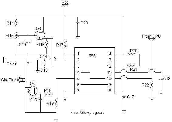
Same thermal load, just split differently. What would you do Incidentally, the circuit I came up with works quite well. It charges at the specified 0. 3A until cell temperature reaches ~100*F (via thermistor). At that point, the circuit cuts the charge and latches "off", so even when the cells cool, the circuit will not start charging again. You reset the latched circuit via a momentary N. C. switch. I`ll provide the schematic once everything is worked out powersupply-wise if anyone cares. I`m using my regulated bench supply right now, but I want the end result to be portable, therefore small, and want it to have its own built-in supply.
The transformer will not change maximum output current unless it has two secondary windings connected parallel. With a center tapped transformer you can`t do it. The secondary windings must be separate! Next question: I am a little worried about the higher voltage this will produce. If this transformer provides 6. 3v @ 2A, the smaller load I will be placing on it (~0. 7A total) will cause the output to be higher than 6. 3v. After rectification and at 2A, the output should be 7. 92v (figuring rectifier 0. 7v loss). But since I will only be drawing ~0. 7A total, the output will be closer to 9v DC, if not higher. I know I could regulate the supply and feed the rest of the circuit true 6v, but I thought that splitting the thermal load across the two cc transistors would be preferable (only have to heatsink the two transistors).
If I regulate it first, the cc transistor disspation will be lower true, but will still need to be on a heatsink, as well as the regulator. Same thermal load, just split differently. What would you do The transformer will not change maximum output current unless it has two secondary windings connected parallel.
With a center tapped transformer you can`t do it. The secondary windings must be separate! Ok, thanks. I somehow got it stuck in my head that if a transformer was rated 12. 6v @ 1A (12. 6w), that wiring the secondary for full wave rectification would reduce the voltage by half, but increase the available current by the same amount, so 2A. That actually works more in my favor since 0. 7A load is pretty close to the 1A rating, so the transformer will be loaded more, and the voltage will be closer to the area I want.
I might not even need regulation. And actually, if the voltage is close enough, I won`t be able to use a regulator since dropout will become a concern. I was more concerned with power dissipation in a small area. If the unregulated voltage was 9v, and I wanted 6v, th 🔗 External reference
Related Circuits
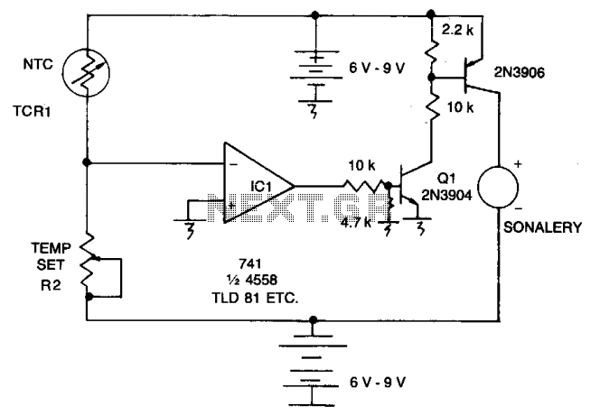
As the resistance (Rl) increases with a decrease in temperature, the output of integrated circuit IC1 becomes positive, activating transistor Q1. When Q1 conducts, it also triggers transistor Q2, which in turn activates the audible alarm. The threshold level...
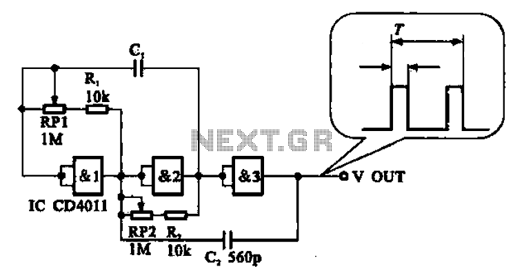
An adjustable pulse generator circuit is presented, which produces a periodic signal with independently adjustable pulse widths. The electrical path allows for modifications to the signal period through the adjustment of RP1. Additionally, RP2 can be altered to change...
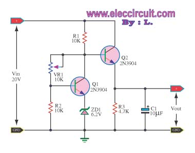
This circuit maintains a constant voltage, with an adjustable output voltage. It serves to reduce the input voltage while keeping the voltage constant. The amplifier model used is the Q1 2N3904 in a common-emitter configuration. This configuration allows the...
All of my turbine starts before the research on the ECU involved a very successful spark ignition. I thought (only briefly) of trying to add spark ignition to the ECU, but the mixture of delicate logic circuitry and perhaps...
This power supply is designed as either an auxiliary or a permanent power supply for various common circuits that require a stabilized DC voltage ranging from 3 to 30V, provided that the current consumption does not exceed 3A. Additionally,...
The original claim indicated that a pentode-connected version is not optimal. However, it was stated that the Mullard 5-10 is not considered optimal. The discussion revolves around the performance evaluation of different amplifier configurations, particularly focusing on the pentode connection...