
Adjustable pulse generator circuit
The adjustable pulse generator circuit typically consists of a few key components: resistors, capacitors, and operational amplifiers or timers, such as the 555 timer IC. The circuit operates by generating a square wave output, where the frequency and duty cycle can be modified according to the desired application.
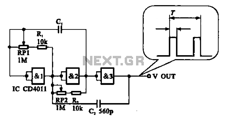
In this configuration, RP1 serves as a variable resistor that adjusts the timing capacitor's charge and discharge cycle, effectively changing the period of the output waveform. This allows for fine-tuning of the frequency while maintaining the desired characteristics of the pulse. The second potentiometer, RP2, adjusts the pulse width by modifying the discharge time of the capacitor, thus allowing independent control over the width of the output pulses.
The frequency of the generator can be calculated using the formula:
\[ f = \frac{1.44}{(R1 + 2RP1) \cdot C} \]
where \( R1 \) is a fixed resistor, \( RP1 \) is the variable resistor, and \( C \) is the timing capacitor. The output frequency can be further referenced against the values provided in Table 16-2, which outlines suitable capacitor values for achieving specific frequency ranges.
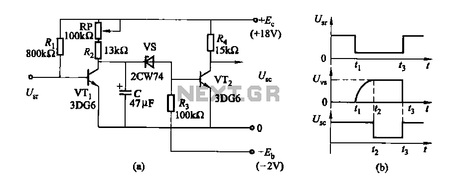
This type of pulse generator is widely used in various applications, including clock generation for digital circuits, signal modulation, and testing of electronic components. The ability to adjust both the frequency and pulse width independently makes it a versatile tool in electronic design and experimentation.Adjustable pulse generator circuit Shows an adjustable pulse generator circuit, which is a periodic signal and the pulse width can be adjusted independently of each other and t he electrical path, can be adjusted to change the period of the signal RP1 n can be adjusted to change the pulse RP2, but not affect the output frequency of the generator. Table 16-2 lists the different C. The value of the frequency range available for reference.
Related Circuits
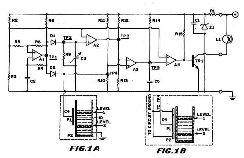
Figure 1 (A) depicts the circuit diagram of one embodiment of the fluid level detector designed. The circuit is typically powered by a 12-volt automobile battery, which is reduced to a 5-volt DC source using a voltage regulator consisting...
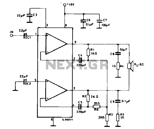
The schematic illustrates a 12 W Bridge Amplifier circuit diagram utilizing the TDA2007A, a class AB dual audio power amplifier. This amplifier is specifically designed for stereo applications in music centers, television receivers, and portable radios. As stated in...
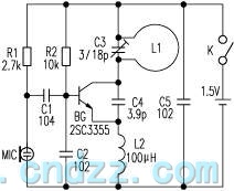
The loop antenna L1 is utilized for emission and also functions as the oscillation coil. The high-frequency current flowing through the antenna is synchronized in resonance with the oscillation frequency, ensuring optimal emission performance. Practical applications indicate that the...
The delay time ranges from 0.5 to 3.5 seconds, which can be adjusted using the potentiometer RP to modify the delay duration. The circuit utilizes a timing mechanism that allows for the adjustment of delay intervals between 0.5 seconds and...
The input impedance of AC-coupled operational amplifier (op-amp) circuits is primarily determined by the resistance that establishes the DC operating point. When using CMOS op-amps, the input impedance is high, reaching up to 10 MΩ in current op-amps. For...

Building a signal generator is an essential project for any analog DIY enthusiast. While already possessing a bench signal generator, the intention was to create a compact, battery-powered device for quickly testing new effect designs. An enclosure from a...
Warning: include(partials/cookie-banner.php): Failed to open stream: Permission denied in /var/www/html/nextgr/view-circuit.php on line 713
Warning: include(): Failed opening 'partials/cookie-banner.php' for inclusion (include_path='.:/usr/share/php') in /var/www/html/nextgr/view-circuit.php on line 713