
KA2211 5.8W Stereo Audio Amplifier
The schematic for the 5.8W stereo power amplifier features the KA2211 integrated circuit, which is designed for driving speakers in consumer audio applications. This amplifier is capable of delivering a total output of 11.6W when both channels are utilized to their maximum capacity. The KA2211 operates with a supply voltage typically in the range of 12V to 24V, allowing for flexibility in power supply design.
The input stage of the amplifier circuit is configured to accept audio signals from various sources, such as smartphones, computers, or other audio devices. Capacitors are used at the input to block any DC offset, ensuring that only the AC audio signal is amplified.
The KA2211 features built-in short-circuit protection and thermal overload protection, enhancing the reliability of the amplifier in various operating conditions. The output stage is designed to drive low-impedance loads, making it suitable for use with standard speakers.
For optimal performance, the circuit includes feedback components that stabilize gain and reduce distortion, ensuring high-quality audio output. Additionally, bypass capacitors are placed near the power supply pins of the KA2211 to filter out any noise and provide a stable voltage to the amplifier.
Overall, the 5.8W stereo power amplifier schematic using the KA2211 is a robust solution for compact audio amplification needs, suitable for a range of applications from portable speakers to home audio systems.The following schematic is the diagram of 5.8 stereo power amplifier based on Samsung IC KA2211. The 5.8W is the power output on each channel, it means that the output will be 2 x 5.8W (maximum). About KA2211: KA2211 is a dual audio power am.. 🔗 External reference
Related Circuits
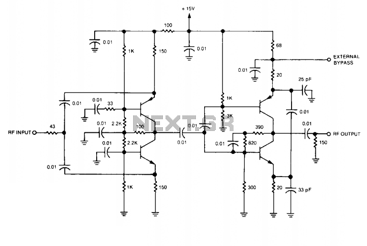
This wideband RF isolation amplifier has a frequency response of 0.5 to 400 MHz ± 0.5 dB. This two-stage amplifier can be utilized in applications that require high reverse isolation, such as receiver intermediate-frequency (IF) strips and frequency distribution...
A high-quality FM stereo transmitter circuit schematic utilizing the BA1404 FM transmitter integrated circuit (IC). This circuit is straightforward to assemble, requiring only a few external components. The FM stereo transmitter circuit based on the BA1404 IC is designed to...
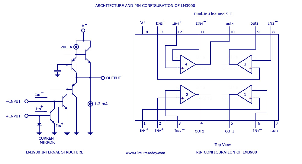
A simple multi-channel audio mixer circuit utilizing the LM3900 quad amplifier is presented below. The circuit features a four-channel quad amplifier (LM3900) with two microphone audio inputs and two direct line inputs. By paralleling additional circuits, the number of...
The circuit was designed to create an audio mixer that can be assembled in modules while providing 6 or more input channels. An audio mixer is a device used to combine multiple audio signals into a single output. The audio...
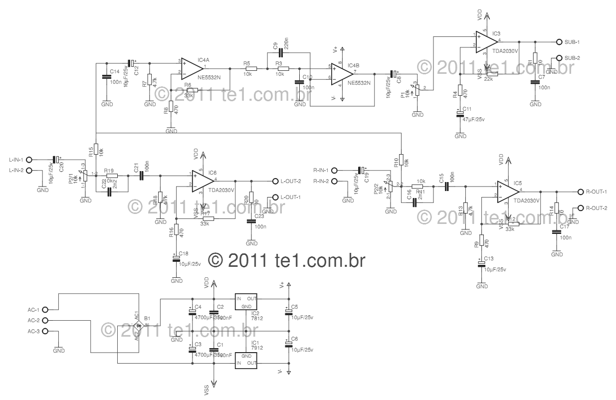
This circuit is a complete application for a 2.1 amplifier system, consisting of two satellite speakers powered by a TDA2030 and one subwoofer. This 2.1 system is commonly utilized in commercial applications as an amplifier for computers, enhancing audio...
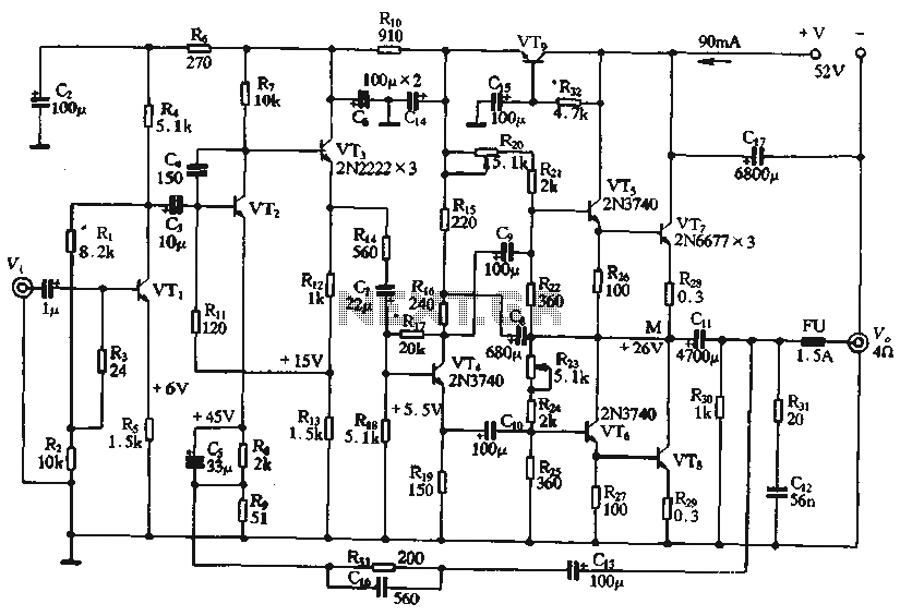
The circuit depicted in the figure is a highly technical OTL (Output Transformer-Less) amplifier circuit. It features a frequency response range of 10 Hz to 100 kHz and exhibits a total harmonic distortion of less than 0.1%, which is...