
Pull transistor relay delay circuit diagrams
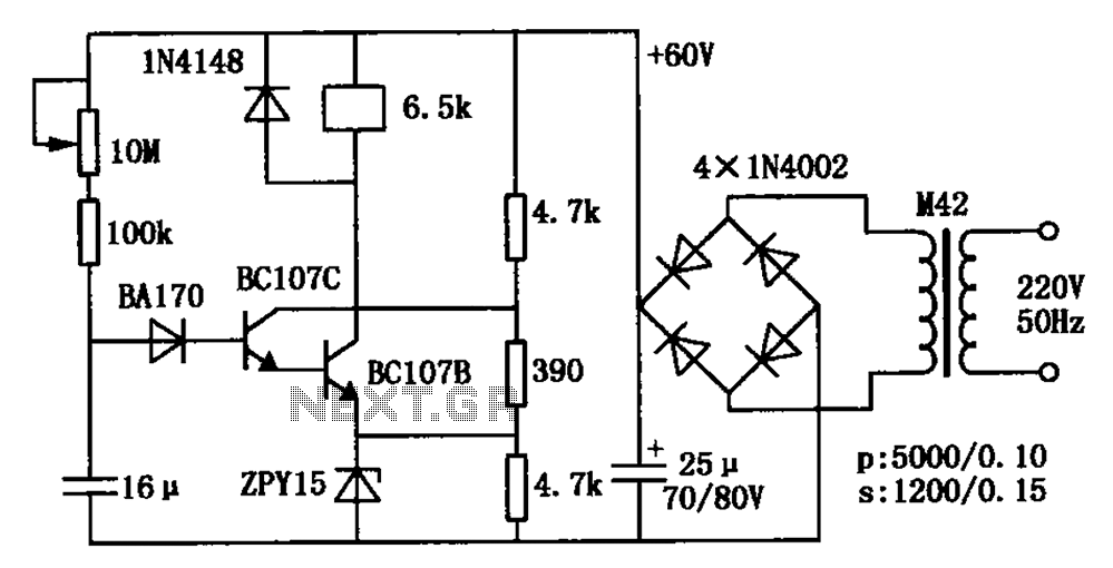
The relay delay pull transistor circuit operates on the principle of a timing delay created by the charging of a capacitor. Upon power-up, the circuit begins with the 16 µF capacitor uncharged, resulting in zero voltage across its terminals. This state keeps both transistors in the off state, preventing any current from flowing through the relay coil, thus keeping the relay deactivated.
As the circuit remains powered, the capacitor begins to charge through the resistor connected in series. The time constant of this charging process is influenced by the values of the capacitor and the resistor. The voltage across the capacitor increases gradually, following an exponential curve defined by the formula V(t) = V_max(1 - e^(-t/RC)), where V_max is the supply voltage, R is the resistance, and C is the capacitance.
Once the voltage across the capacitor reaches the threshold level necessary to turn on the transistors, both transistors switch to the on state, allowing current to flow through the relay coil. This action energizes the relay, closing its contacts and activating any connected load. The duration of the delay, which can be adjusted up to 60 seconds, is determined by the values of the capacitor and the 10 MΩ resistor. By changing the resistance, the charging time of the capacitor can be modified, thus varying the delay before the relay is pulled in.
This circuit is particularly useful in applications where a delayed response is required, such as in timers, automated systems, or safety interlocks, ensuring that certain actions occur after a predetermined period following the application of power. As shown relay delay pull transistor circuit. Just power, 16 F capacitor voltage is zero, two transistors are off, the relay does not operate. With 16 F capacitor charge, over a period of time to which the voltage reaches a high level, two transistors are turned on, the relay delay pull. The delay time of up to 60s. Delay time can be adjusted by 10M resistor.
Related Circuits
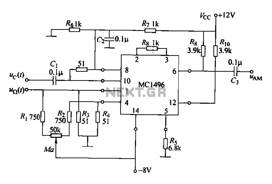
The configuration of the AM MC1496 analog multiplier integrated circuit is illustrated in Figure 21-39. It features a two-input channel where the DC levels of the pins are set at 6V, allowing it to function as a carrier channel...
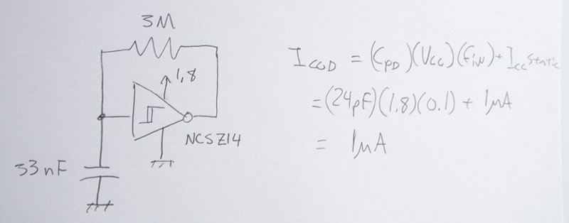
The power supply varies, and the circuit must operate at under 10 µA of current (excluding the capacitor charging). It triggers a Silicon Controlled Rectifier (SCR) every 10 to 30 seconds as long as the power supply is above...
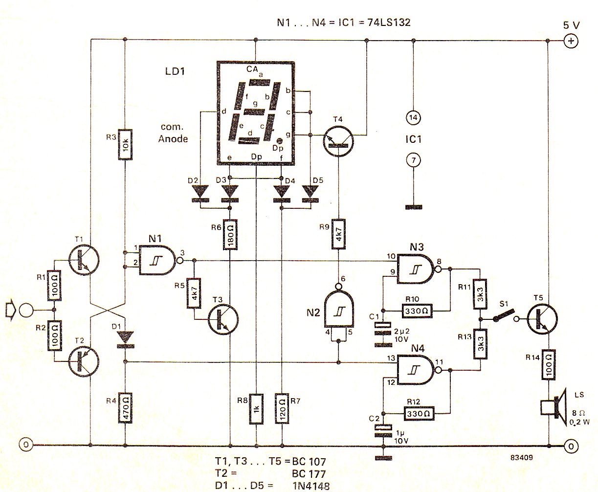
When the input signal is at logic high (1), the display indicates `H`, and the loudspeaker emits a note that is one octave higher than the low tone. The operation of the circuit can be observed in the circuit...
To complement the 60 Watt MOSFET audio amplifier, a high-quality preamplifier design was necessary. A discrete components topology using +24V and -24V supply rails was chosen, minimizing the transistor count while still achieving low noise, very low distortion, and...
This circuit transmits a continuous audio tone on the FM broadcast band (88-108 MHz), which can be utilized for remote control or security applications. The circuit draws approximately 30 mA from a 6-9 volt battery and has a reception...
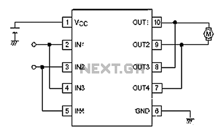
A simple motor control project for forward and backward drive can be implemented using the LB1948M motor driver IC, which features two channels for motor control. The LB1948M is an ideal choice for 12V motor drive systems and can...