
Electronic Siren Circuit

The circuit described operates as a simple sound generator that mimics the sound of a police siren through an oscillating process involving two transistors: the BC108B and the 2N3702. The BC108B acts as the primary control element, while the 2N3702 serves as a secondary switch that enhances the oscillation effect.
The initial state of the circuit, with the 10 µF capacitor discharged, ensures that no current flows through the transistors. When the push button is activated, the capacitor begins to charge through the 22 kΩ resistor, leading to a gradual increase in voltage at the base of the BC108B. This slow turn-on characteristic is crucial for achieving the desired sound effect, as it allows for a gradual rise in tone.
Upon releasing the push button, the capacitor discharges through the base resistors, which controls the turn-off time of the BC108B. The feedback loop created by the interaction between the two transistors and the capacitors is essential for generating the oscillating sound. The rapid switching of the 2N3702, triggered by the collector voltage drop of the BC108B, creates a quick response that enhances the sound modulation.
The 22 nF capacitor plays a vital role in this feedback loop, as it couples the collector voltage of the 2N3702 back to the base of the BC108B. The interplay of charging and discharging between the capacitors and the transistors leads to a continuous cycle of sound production, with the frequency of oscillation determined by the capacitor values and the resistors in the circuit.
The overall design allows for flexibility in sound production; varying the component values can yield different siren tones, making it adaptable for various applications. The use of a loudspeaker with different impedance ratings can also affect the output sound characteristics, providing opportunities for further experimentation and customization.The sound produced imitates the rise and fall of an American police siren. When first switched on the 10u capacitors is discharged and both transistors are off. When the push button switch is pressed to 10u capacitor will charge via the 22k resistor. This voltage is applied to the base of the BC108B which will turn on slowly. When the switch is re leased the capacitor will discharge via the 100k and 47k base resistors and the transistor will slowly turn off. The change in voltage alters the frequency of the siren. The oscillator action is more difficult to work out. As the BC108B transistor switches on its collector voltage falls and so the 2N3702 transistor is switched on.
This happens very quickly ( less than 1us). The 22n capacitor will charge very quickly as well. As this capacitor is connected between the collector of the 2N3702 and the base of the BC108B, it soon reaches almost full supply voltage. The charging current for the capacitor is then much reduced and the collector emitter voltage of the 2N3072 is therefore increased; the collector potential will fall.
This change in voltage is passed through the 22n capacitor to the base of the BC108B causing it to come out of saturation slightly. As this happens its collector voltage will rise and turn off the 2N3072 transistor more. This continues until both transistors are off. The 22n capacitor will then discharge via the 100k, 22k resistor, the closed push button switch, 9V battery, the speaker and 56 ohm resistor.
The discharge time takes around 5-6msec. As soon as the 22n capacitor is discharged, the BC108B transistor will switch on again and the cycle repeats. The difference in voltage at the collector of the BC108B (caused by the charging 10u capacitor) causes the tone of the siren to change.
As the 10u capacitor is charged, the tone of the siren will rise, and as it is discharged, it will fall. A 64 ohm loudspeaker may be used in place of the 8 ohm and 56 resistor, and the values of components may be altered to produce different sound effects.
🔗 External reference
Related Circuits

This is a design circuit for a soft light dimmer. The circuit utilizes the IGBT STGP10N50A and the TS555 timer as the main components. The timer is triggered by the zero crossing voltage pulse. The time constant, determined by...
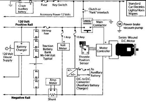
After charging the batteries for many hours with the 12V charger and PowerCheqs, a drive of about 5 miles resulted in the low battery light activating. The PakTrakr indicated that the battery adjacent to the most positive battery required...
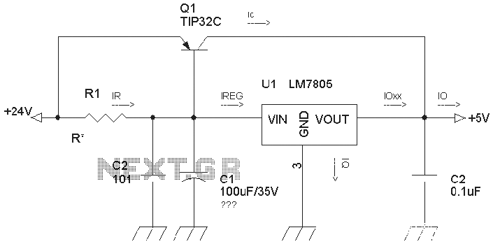
The circuit is a common three-terminal linear regulator expansion flow circuit. In practical applications, it may encounter some well-considered or lower false failures. 1. Disadvantages of this power supply: 1.1 This power supply is a linear regulator...
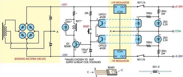
This circuit was designed to protect a dual rail power supply from shorts across the two rails. It uses an optocoupler to monitor each supply rail, with the internal LEDs powered from ZD2 and ZD3 and the associated resistors....
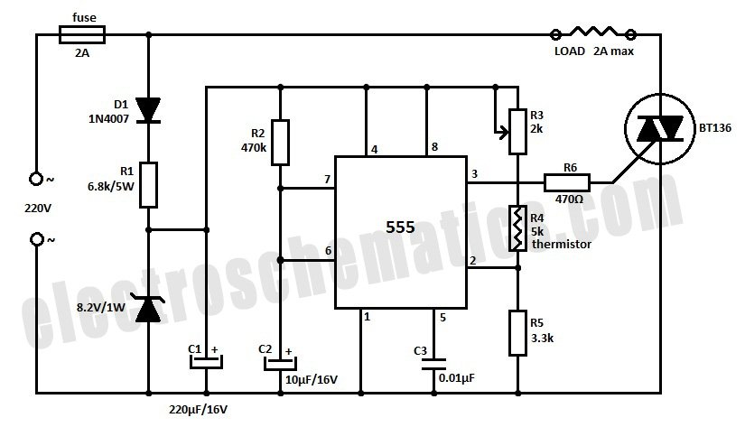
Construct a temperature controller circuit using the 555 integrated circuit (IC) in combination with a thermistor resistor divider. The benefit of this design is that it does not require a well-regulated power supply. The resistor divider network comprises an...
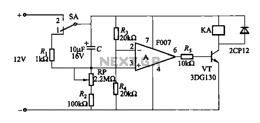
A delay circuit utilizing an operational amplifier functions as a comparator, providing high timing accuracy. The timer's delay range is from 1 to 30 seconds. The delay time is determined by resistors Ri, RP, and capacitor C. By adjusting...
Warning: include(partials/cookie-banner.php): Failed to open stream: Permission denied in /var/www/html/nextgr/view-circuit.php on line 713
Warning: include(): Failed opening 'partials/cookie-banner.php' for inclusion (include_path='.:/usr/share/php') in /var/www/html/nextgr/view-circuit.php on line 713