
the design of the intellectual wireless signal transducer of ARM
The intellectual wireless signal transducer serves as a critical component in various sensor applications, allowing for the effective monitoring and transmission of data. The dual output capability of 4-20 mA and 0-60 mV enables compatibility with a wide range of sensors and devices, facilitating integration into existing systems. The 4-20 mA signal is widely recognized in industrial applications for its robustness against electrical noise and its ability to transmit over long distances without significant signal degradation. Conversely, the 0-60 mV signal, typically associated with thermocouples, provides high sensitivity and precision for temperature measurement, making it ideal for applications requiring fine resolution.
The recuperation circuit plays a vital role in conditioning the incoming signals to ensure they are suitable for digitization. This circuit amplifies the weak millivolt signals, ensuring they reach an appropriate level for processing by the A/D converter. The multiplexer allows for the selection between the two input signals, ensuring that the MCU receives the correct signal for further processing. The A/D converter then digitizes the analog signals, enabling their manipulation and analysis by the MCU.
The GPRS modem interface circuit is essential for remote communication, allowing the processed data to be transmitted to control centers or monitoring stations. This capability enhances the system's functionality, enabling real-time data access and remote management of the sensor network.
Overall, the design of this intellectual wireless signal transducer emphasizes flexibility, accuracy, and reliability, making it suitable for a wide range of professional applications in monitoring and control systems. The careful consideration of signal types and processing methods ensures that the system can adapt to various operational environments and requirements.The intellectual wireless signal transducer was for major transducer and typical sensor to output signal design, so analyze their own outcoming signals at first. Usually the output of the transducer is 4- 20mA standard electric current signal. And to sensor, there are very many types of its outcoming signal. Seeing that the target that this system design faces, with strong points to professional application, employ less
non-electric and formal signals, greater voltage signals to be considered. In addition, as to the more common frequency signal, while designing the systematic prototype machine, has not considered either, can join in the reseach of the prototype machine of this goods in process, in order to increase the flexibility of the system. Generalized analysis, the focal point is the weak voltage signal. Where is that signal range of the weak voltage directed against how to confirm system design Generally speaking, the voltage signal of mV grade is considered to be the weak voltage signal, but this concept is very fuzzy, not easy quantitative design.
Might as well take thermocouple as examples to analyze here according to applied extensive intensity, representativeness and normal intensity. What thermocouple is produced is voltage Electric potential The signal, belong to tempolabile millivolts of weak signals, Table 1 is commonly used temperature measurement limits and correspondent thermoelectric force ranges of different thermocouple.
Can be found out from the table, the output thermoelectric force of thermocouple is basically within the range of 0- 60mV, so, can be thought 0- 60mV to have better representativeness, can cover much application environment, also should be regarded as another a type of signal of sysin. There are two kinds of so systematic forward end input signals: 4- 20mA standard electric current signal and 0- 60mV voltage signal.
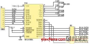
These two kinds of signals are after different one is recuperated the circuit and recuperate the voltage signal that input the quantum for the suitable A/D chip, strobe analog to digital converter by the multiple-way switch, then deal with through MCU, all right and other site plant or control centers of end carry on communication. The systematic principle chassis picture is shown in Fig. 1. Recuperate circuit, AD chance-over circuit, GPRS MODEM interface circuit these respects and introduce the design of the circuit of the hardware from the signal separately below.
The function that the signal recuperates the circuit is that this two-way input signal is amplified and dealt with aforesaid 4- 20mA standard electric current signal and 0- 60mV voltage signal, and realize that strobes input, change to it usedly for postern AD through the multiple-way switch. Because this system designs dynamic range of input signal as 0- 60mV, A/D 🔗 External reference
Related Circuits
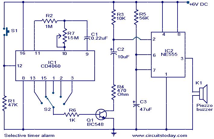
A timer circuit utilizing the IC 4060 is presented. The IC 4060 functions as a 14-stage binary counter equipped with an integrated oscillator. The components R2, R7, and C1 are responsible for determining the oscillator's frequency, causing the outputs...
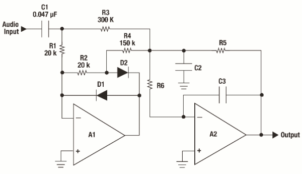
Audio metering is prevalent in various devices that play or record audio, ranging from cell phones displaying bar graphs of audio output levels to home stereos with flashing LEDs and live broadcasting equipment. Multiple standards exist for audio metering,...
Its an adaptation of the 2X 16 LCD project, by adding a ferrite loop antenna, two resistors, and a capacitor. Here the display shows the output of the 10 bit scanning voltmeter with Minimum Mass Wireless Coupler. Both the...
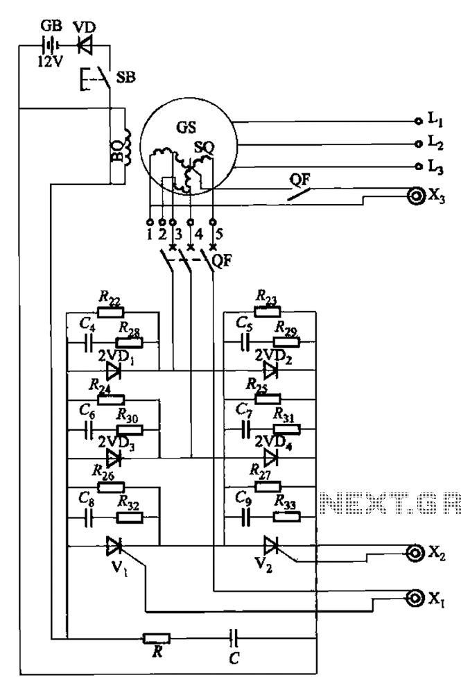
The setup is connected to separate stator windings of a harmonic generator, which leads to a thyristor rectifier supply for the third harmonic voltage, positioned after the motor field. The output voltage varies with changes in the winding harmonics...
The wireless transmitter circuit utilizes transistor T1 (BF494) as a low-power variable-frequency VHF oscillator. A varicap diode circuit is incorporated to modify the frequency of the FM transmitter and to facilitate frequency modulation using audio signals. The output power...
The schematic diagram below illustrates a complete barometric pressure signal conditioner that operates from a single 1.5V battery. It provides optimal accuracy. The barometric pressure signal conditioner circuit is designed to convert the analog signal produced by a barometric pressure...