
Keypad Controlled Switch No2
The Keypad Controlled Switch No2 Circuit is designed to allow users to control a load through a keypad interface. The circuit utilizes a microcontroller or a dedicated keypad decoder to interpret the key presses. When a specific key is pressed, the microcontroller activates a relay, which in turn controls the power to the connected load.
The circuit typically includes the following components:
1. **Power Supply**: A voltage regulator may be used to ensure stable operation within the specified voltage range (5-15V).
2. **Keypad**: A matrix keypad is commonly employed, allowing for multiple key inputs while minimizing the number of input pins required.
3. **Microcontroller/Decoder**: This component processes the keypad inputs and controls the relay. It can be programmed to recognize specific key sequences for different functions, such as turning the load on or off.
4. **Relay**: A relay suitable for the chosen supply voltage is used to switch the load. The relay should be rated for the load current and voltage to ensure safe operation.
5. **Load**: The device or circuit that will be controlled by the relay, which could be anything from lights to motors.
The design considerations include ensuring that the relay's coil voltage matches the power supply voltage and that the microcontroller's output pins are capable of driving the relay, either directly or through a transistor for higher power applications. Additionally, debounce logic may be implemented in the software to prevent multiple activations from a single key press.
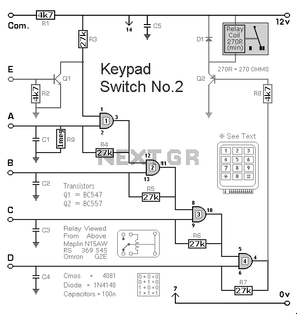
This circuit can be further enhanced with features such as LED indicators to show the status of the load or additional safety mechanisms to prevent unauthorized access or accidental activation.Keypad Controlled Switch No2 Circuit The circuit is drawn with a 12-volt supply - but it will work at anything from 5 to 15-volts. All you have to do is choose a relay suitable for the supply voltage you want to use. Replace the.. 🔗 External reference
Related Circuits
This switch will suit the Modular Burglar Alarm circuit. However, it also has other applications. The Keypad must be the kind with a common terminal and a separate connection for each key. On a 12-key pad, look for 13...
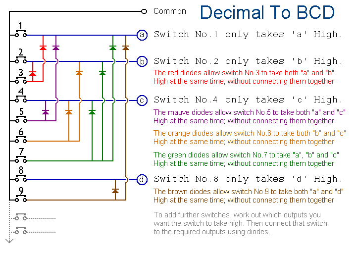
When any particular key is pressed, its value will appear in BCD form at the outputs (A, B, C & D). It will remain there until another key is pressed. The 12 keys produce outputs up to "1011". Extended...
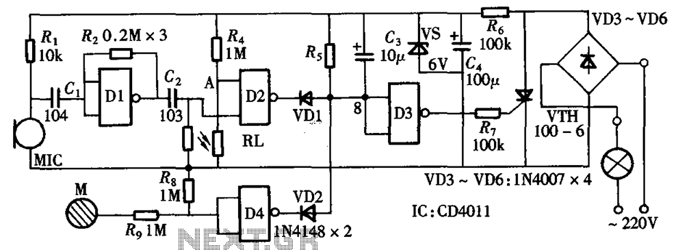
The circuit integrates sound and light control with touch functionality, creating a fully operational delay section light switch circuit. It consists of light control, voice circuits, and a touch control circuit, all triggered by a thyristor switch. The described circuit...
The RF engineer occasionally needs to find an instrument that can reliably and quickly test a low-frequency quartz crystal unit. This equipment is often challenging to locate, leading engineers to consult electronic circuits handbooks for schematics that can perform...
Almost any 2x16 character LCD module with Hitachi HD44780 controller chip will work. The LCD pin numbers on the schematic are not valid for all LCD modules. Please check the actual signal names on your particular LCD module. The...

This design uses a smart card to enable a relay. A Nutchip recognizes its mating smart card among thousand similar ones, because you choose the code to be programmed in the card's memory. No specialized knowledge is necessary, as...