
5 Digit Alarm Keypad
The described circuit utilizes a keypad interface to activate a modular burglar alarm system. The keypad must consist of a common terminal and individual connections for each key, specifically designed to facilitate the selection of a unique code from a set of five keys. The configuration allows for a significant number of possible combinations, as it can incorporate non-numeric symbols, resulting in nearly 100,000 different codes.
The connection of the keypad to the circuit involves linking the selected keys, labeled A, B, C, D, and E, to designated points on the circuit. The common terminal is connected to resistor R1, while the remaining keys are wired to point F. This setup ensures that when the designated sequence of keys (A, B, C, and D) is pressed in the correct order within a time frame defined by capacitor C1 and resistor R2, the system will activate.
The timing component, consisting of C1 and R2, is critical for the operation of the system, allowing a window of approximately 10 seconds for the user to input the code. When the correct sequence is entered, current flows through resistor R11, which activates transistor Q6. The activation of Q6 subsequently energizes a relay, enabling the alarm system.
Once the relay is energized, it maintains its state by providing base current to Q6 through resistor R12. This self-latching mechanism ensures that the alarm remains activated until it is intentionally deactivated, providing a robust security feature for the burglar alarm system. The schematic design emphasizes simplicity and reliability, making it suitable for various applications beyond just alarm systems.This switch will suit the Modular Burglar Alarm circuit. However, it also has other applications. The Keypad must be the kind with a common terminal and a separate connection for each key. On a 12-key pad, look for 13 terminals. The matrix type with 7 terminals will NOT do. Choose the five keys you want as your code, and connect them to `A, B, C, D & E`. Wire the common to R1 and all the remaining keys to `F`. Because your choice can include the non-numeric symbols, almost 100 000 different codes are available. The Alarm is set using the first four of your five chosen keys. When `A, B, C & D` are pressed in the right order and within the time set by C1 and R2 (about 10 seconds), current through R11 switches Q6 on. The relay energizes, and then holds itself on by providing base current for Q6 through R12. The 12 🔗 External reference
Related Circuits

This circuit utilizes a 555 timer integrated circuit (IC) as an alarm system designed to deter theft of luggage and prevent unauthorized entry into homes. The alarm is activated when a thin wire, typically as fine as a human...

The circuit illustrated in Figure 1 generates a precise variable-frequency sine wave intended for use as a general-purpose reference signal. It incorporates an 8th-order elliptic switched-capacitor low-pass filter (IC3), which is clocked by a 100 kHz square wave produced...

The CD4538 is a dual Monostable Multivibrator. When triggered, the chip generates a single pulse or a high-low event. The T+ pin (pin 4) of U1a serves as the positive edge trigger input, while the T- pin (pin 5)...

When this car alarm circuit is activated, it remains active for 80 seconds. There is a 15-second delay for the driver to enter and deactivate the alarm. All timings can be easily modified. The circuit utilizes two NE555 timers,...
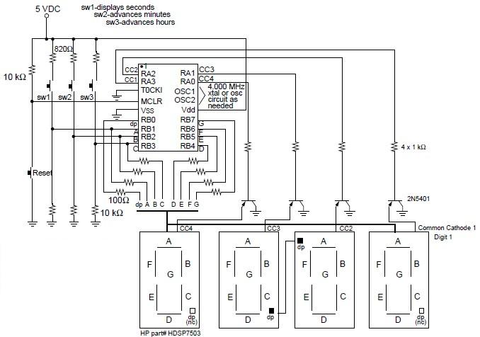
A digital clock project utilizing the PIC16C54 microcontroller can be constructed using the provided circuit diagram. This electronic project features a time-of-day clock that includes four seven-segment LED displays and three input switches. Additionally, there is a reset switch...
The CD4538 is a precision monoflop available in DIP-16 and SMD-16 packages. It offers stable performance with fewer required external components and strong logic functionality. The chip integrates two independent single-shot circuits, making it widely applicable in counting, division,...