
Knight Rider Lights
This setup is ideal for running off a car battery.
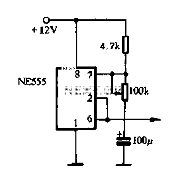
The circuit described utilizes a 555 timer configured in astable mode, which generates a continuous square wave output. This output serves as a clock signal for the CD4017 decade counter, which counts the pulses and activates its outputs sequentially. The 10K resistor connected between the output of the 555 timer and the clock input of the 4017 ensures that the pulses are appropriately limited in amplitude, preventing damage to the IC from excessive current.
The CD4017 has ten output pins (Q0 to Q9), each capable of driving a load. In this application, LEDs are connected to these outputs. Since certain LEDs need to remain illuminated for multiple counts, diodes are employed to ensure that current flows only in the desired direction, thus preventing any potential short circuit that could arise from multiple outputs being activated simultaneously.
To ensure the counter resets to zero upon power-up, a capacitor and resistor are connected to the reset pin (pin 15) of the 4017. This configuration allows the capacitor to charge and subsequently reset the counter, ensuring reliable operation from the moment power is applied.
For applications requiring higher power outputs, the ULN2001N Darlington driver IC can be utilized. This IC can drive larger loads, such as 12V bulbs, by providing sufficient current gain. Each output of the ULN2001N can be activated by a low-level signal from the CD4017, making it suitable for controlling higher voltage devices without directly interfacing with the low-voltage logic levels of the CD4017.
Overall, this circuit is particularly well-suited for battery-powered applications, such as automotive lighting systems, where the 12V bulbs can be directly powered by the outputs of the ULN2001N, creating a versatile and efficient lighting solution.The 555 timer IC is connected for Astable Operation, the clock pulses are fed to the 4017 IC via the 10K resistor. The 4017 is a 10 stage counter, each of the outputs is connected to the appropriate LED, as some LEDs need to be on for more than one count, we use diodes to avoid a short circuit situation between outputs.
The capacitor and resistor on pin 15 of the 4017 are used to reset the counter to zero at initial power up. The ULN2001N used on the bulb version is a seven channel Darlington Driver IC, a small signal on one of the inputs is enough to drive the bulb on the output.
You can use 12V bulbs for the output, simply substitute the IC for the LEDs, the bulbs are then connected to the IC's outputs. This set up is ideal for running off a car battery. 🔗 External reference
Related Circuits
This project develops a Christmas lights controller for GE Color Effects lights, enabling programmed control of up to eight sets of lights. It includes a function-specific language for programming light patterns and an emulation environment for testing programs before...

The circuit utilizes a four-way slowly dimming LED driver integrated with iU shoe production and a Qis four flashing lights string controller. The C3484 manifold is specifically designed to operate Ji lights with four lights that flash and slowly...
An intriguing lighting solution for bicycles, utilizing LEDs. It features low power consumption and includes a circuit diagram for an electronics project, operating at 9V, utilizing the NE555 timer. The bicycle lighting circuit employs a NE555 timer IC configured in...

The circuit operates on 220V AC, utilizing resistors R1 and R2 to create a partial voltage drop. A VD half-wave rectifier converts this AC voltage to approximately 3V DC across capacitor C. An adjustment potentiometer RP is incorporated to...
Automatic color holiday lights circuit The automatic color holiday lights circuit is designed to control the operation of decorative lights during festive seasons. This circuit typically utilizes a microcontroller or a timer to manage the sequencing and color changes...
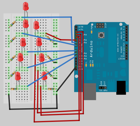
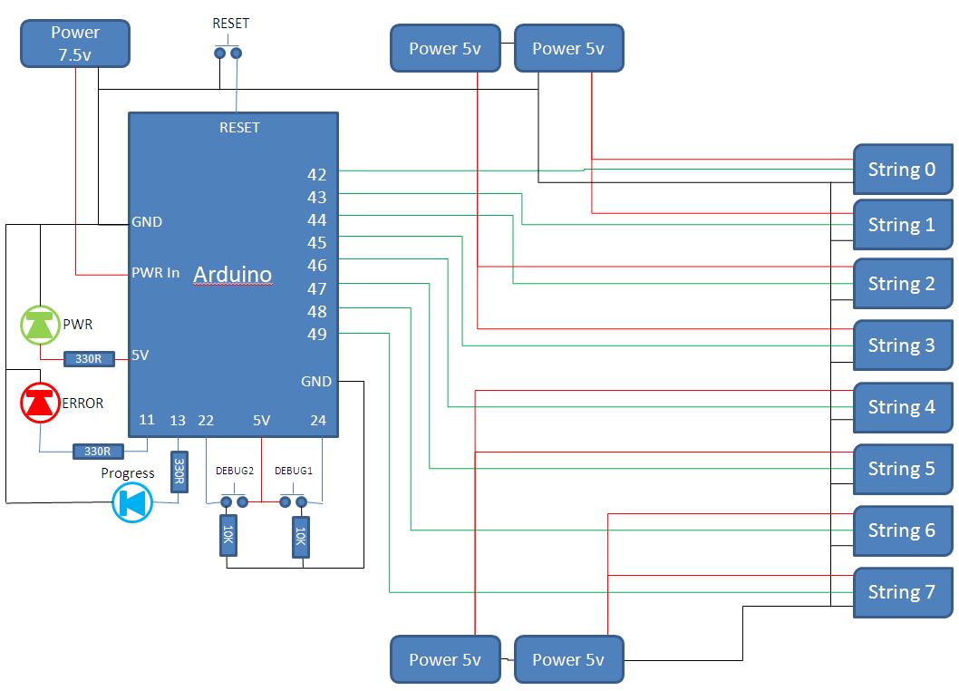
This is the next part in the Arduino learning series, focusing on the use of arrays to create a small Christmas tree ornament with various flashing sequences. This project is suitable for engaging children in basic soldering skills—simply mount...