
Knight Rider lights for model cars

The Knight Rider scanner circuit is designed to create a visually appealing light sequence that mimics the iconic scanning effect seen in the television series "Knight Rider." This effect is achieved by sequentially illuminating a series of six LEDs, which can be arranged in a line or any desired configuration. The circuit utilizes a 7555 timer IC, which is a CMOS version of the classic 555 timer, known for its low power consumption and versatility in timing applications.
The operation of the circuit is based on the astable mode of the 7555 timer, generating a square wave output that controls the LEDs. The frequency of the blinking can be adjusted by selecting appropriate resistor and capacitor values connected to the timer. This configuration allows the user to customize the speed of the LED scanning effect.
The output from the 7555 timer is connected to a series of driver transistors, which amplify the current to drive the LEDs. Each LED is connected through a current-limiting resistor to ensure that it operates within its specified current ratings, preventing damage and ensuring longevity. The circuit can be powered by a standard DC power supply, with the voltage level determined by the specifications of the LEDs and the 7555 timer.
In summary, this Knight Rider scanner circuit not only provides an engaging visual display but also showcases the functionality of the 7555 timer in driving multiple outputs with efficient power management. Proper selection of components will enhance both the performance and reliability of the circuit.This simple circuit drives 6 LEDs in `Knight Rider scanner mode`. Power consumption depends mainly on the type of LEDs used if you use a 7555 (555 CMOS version). 🔗 External reference
Related Circuits
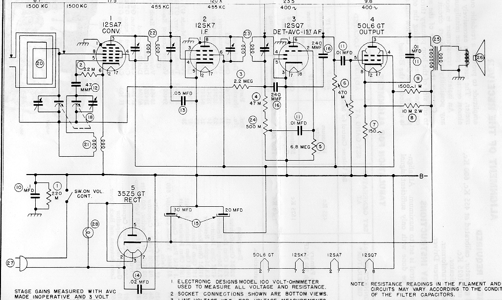
"Black Beauty" is a nickname for a classy Bakelite radio set. It features a dramatic, asymmetrical design with deep wraparound louvers and a bullet-like profile, exemplifying 1940s Streamline design. The radio is undergoing restoration of its electronics and cabinet....

The terminal of R7, indicated by an arrow, must be connected to the desired output pin of IC2 or IC3 to select the number of LEDs or clusters that will form the bar. For instance, to drive seven LEDs...

A 200W lamp switch control operates at a power supply voltage of 220V. It automatically turns the light on or off based on ambient illumination levels, specifically activating at approximately 100 lux. In low light conditions, a time-sensitive resistor...
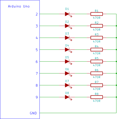
Construct a Knight Rider LED display on a breadboard using an Arduino controller. This is a straightforward circuit designed for beginners in electronics, utilizing an Arduino Uno. The Knight Rider LED display emulates the iconic light sequence from the television...
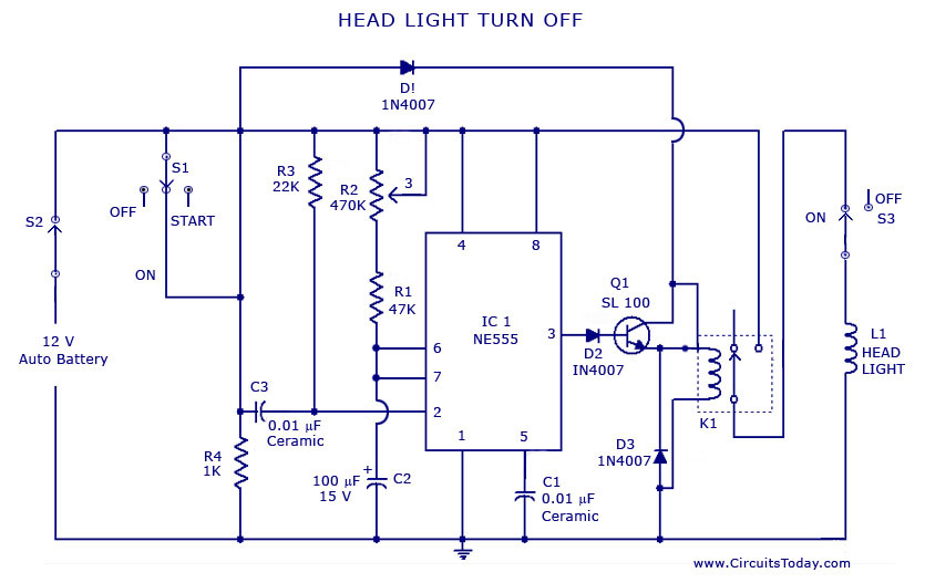
A circuit that can automatically turn off the headlights or lamps of a vehicle after a preset time. This light switching circuit is constructed using a 555 timer integrated circuit (IC). The described circuit utilizes the 555 timer IC in...

The circuit operates with a 220V mains supply through a diode (VDi) configured as a half-wave rectifier. Capacitors C1 to C3 are charged, and due to the lack of full synchronization in the charging process, a pilot thyristor is...