
Knightrider lights for model cars
The circuit for the Knightrider scanner mode employs a 555 timer IC, specifically the CMOS variant (7555), which is known for its low power consumption and versatility in timing applications. The configuration typically used is astable, generating a square wave output that alternates the LEDs in a sequential manner, creating a visual effect reminiscent of the iconic "KITT" scanner from the television series.
The circuit consists of six LEDs arranged in a linear fashion. Each LED is connected in series with a current-limiting resistor to prevent excessive current flow, which could damage the LEDs. The output from the 7555 timer drives a series of flip-flops or a decade counter, which sequentially activates each LED in a specific order, producing the desired scanning effect.
The power supply for the circuit can vary depending on the LED specifications and the design requirements; however, a common voltage range is between 5V and 15V. It is crucial to select appropriate resistors to ensure that the current through each LED does not exceed its rated specifications, typically around 20 mA for standard LEDs.
For enhanced functionality, additional components such as capacitors may be included to stabilize the voltage and improve the timing accuracy of the 555 timer. The choice of LEDs can also affect the overall power consumption and brightness of the display, making it essential to consider the forward voltage and current ratings of the selected LEDs when designing the circuit.
Safety precautions should be observed when assembling and testing the circuit. Proper insulation, the use of breadboards or prototyping boards, and adherence to standard electrical safety practices are recommended to minimize the risk of electric shock or damage to components.This simple circuit drives 6 LEDs in `Knightrider scanner mode`. Power consumption depends mainly on the type of LEDs used if you use a 7555 (555 CMOS version). We are not responsible for any injuries or damage caused by information from this website! Working with electricity is dangerous for your life, especially diagrams related to high voltage! We do not guarantee success in building devices using our diagrams! They are not tested by us. For questions about diagrams use author info below diagram or our contact page. Thank you! 🔗 External reference
Related Circuits
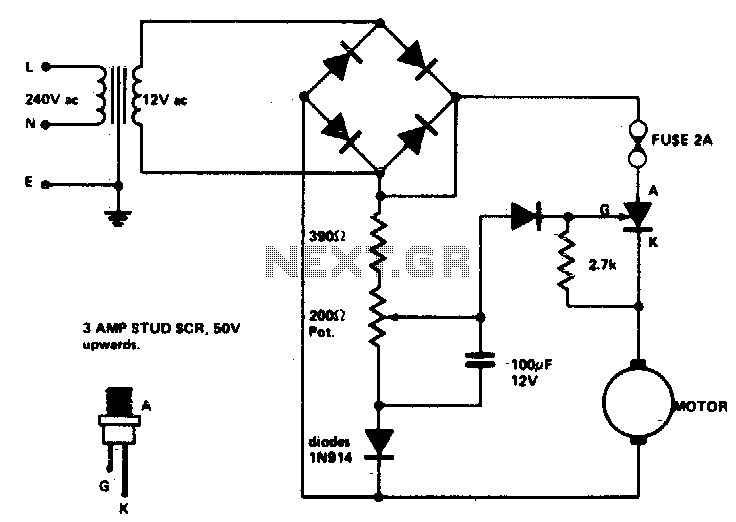
Low voltage speed control provides excellent starting torque and effective speed regulation. Additionally, a reversing switch can be integrated into the motor leads. Low voltage speed control circuits are essential in applications where precise motor control is required, such as...
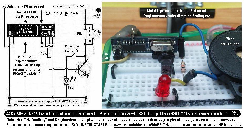
This is a simple 433.92 MHz short-range radio beacon that can be useful for locating downed R/C planes, lost balloons, model rockets, or possibly hidden items. The 433.92 MHz short-range radio beacon circuit is designed to transmit a signal over...
From 230 V AC a DC supply of + 5 V is obtained. The power supply is given to the other blocks. The pulse generator at a particular frequency generates the clock pulses. The clock pulses are counted by...
A 1996 Ford Explorer has non-functional headlights. The vehicle has operational low beams and interior lights. The owner has replaced the bulbs, checked the fuses, relays, and light switch, yet the headlights remain inoperative. Suggestions are requested to identify...
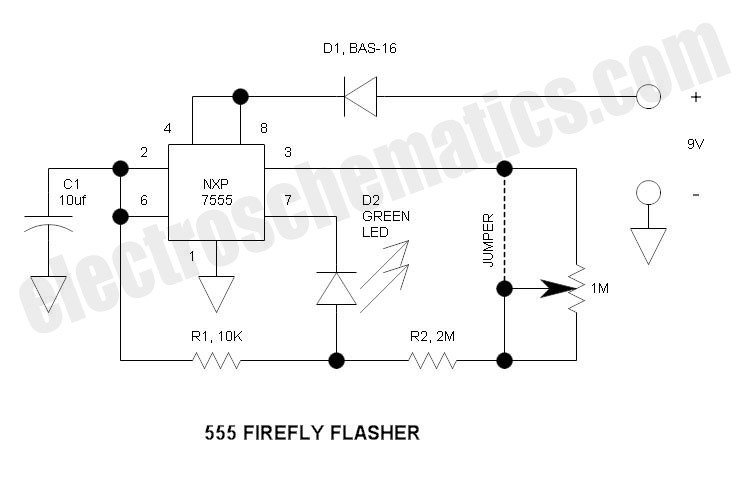
This circuit differs from the standard 555 oscillator circuit by placing the LED in the capacitor reset line (pin 7). This configuration reduces overall current and prevents high peak LED current from draining the battery. The forward voltage drop...
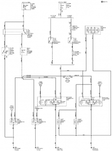
The connection and wiring between each part and component of the exterior lighting system of the vehicle includes elements such as the fusible link, junction block, tail light relay, cruise control, stop light switch, relay box, column switch, rear...