
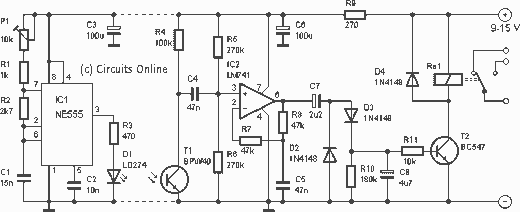
Model Glow Plag driver circuit
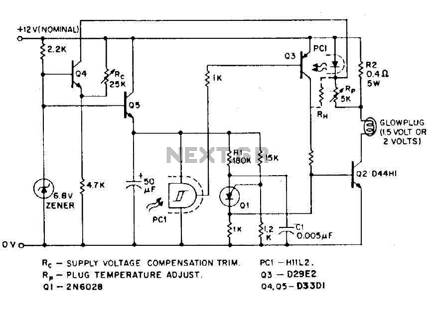
Rather than managing multiple energy sources, model builders typically prefer to use a single 12-volt battery. This battery can supply lower voltages through appropriate electronic step-down transformers (choppers). The pilot light benefits from negative feedback, maintaining a constant temperature during engine start-up, or while operating at different voltages.
In this circuit, a Programmable Unijunction Transistor (PUT) relaxation oscillator activates transistors Q1 and Q2, controlling the output of the chopper at a fixed repetition rate determined by resistors R and capacitor C1. Current flows through the spark plug and the parallel combination of resistor R2 and a current direction indicator associated with a Schmitt trigger. When the glow plug is cold (low resistance), current is high, which biases the Schmitt trigger "on," leading to Q3 providing base support for Q2. Once the glow plug reaches its operating temperature, controllable by its ohmic resistance, the Schmitt trigger is programmed to cut off the base drive to Q2 and Q3.
However, the glow plug's effectiveness depends on the voltage remaining constant, which is not always guaranteed. Transistor Q4 compensates for voltage drops (such as during a cold start) by increasing its collector current, which allows more current to flow through the diode, thereby delaying the cutoff point for the glow plug. This circuit maintains a relatively constant temperature, regardless of whether the glow plug is completely dry or wet, across an input voltage range from 8 to 16 volts. A similar configuration can be used to maintain a constant temperature for larger diesel truck glow plugs (28-volt supply, 12 volts). In this case, additional resistance may be necessary to manage temperature excursions due to hysteresis.
The circuit includes components such as Rc for compensation voltage trimming, Rp for temperature adjustment of the glow plug, and specific transistor models including 2N6028 and D29E2.model airplanes, boats, cars and use of ignition of glow plugs for their miniature (O. Bcc to 15cc) internal combustion engines. These engines happen with the heavy batteries on board, HT coil, and "condenser" spark required for ignition classic, while simultaneously developing much higher RPM (and thus power) as the compression ignition (diesel) engines . The heart of a candle is a coil of platinum alloy filament heated to start the engine by an external battery, or 1.
5 volts or 2 volts. To complete this battery, a second power supply of 12 volts is often necessary to start the engine, together with a third type 6 volt electric fuel pump. Rather than being overwhelmed by these multiple energy sources, the model builder prefer to wear (and buy) a single 12 volt battery, stemming from lower voltages from this by the use of appropriate electronic step-down transformers (choppers). The pilot light and shown it has the additional advantage of (through negative feedback) to maintain a constant temperature independent decision to drown the engine, or age volts while the starter is starting.
In this circuit, the PUT relaxation oscillator turns on transistor Ql Q2 output of the chopper at a fixed repetition rate determined by R and C1. The current then flows through the spark plug and the parallel combination of resistor R2 and the current direction indicator associated with the relaxation HILL Schmitt.
With the cold cap (low resistance), current is high, the hill is biased "on", and Q3 results in order to support the base of Q2. Once the cap has reached operating temperature, which can be controlled by its ohmic resistance, theHllL is programmed (via RJ extinguish, remove base drive of Q2 and Q3.
However, since the glow plug HAVL sense, no resistance, only val id if the voltage is constant, which is not always the case. Transistor Q4 provides adequate compensation in this case, if the voltage drops (during cold start, for example), the collector current of Q4 rises, causing more current through the diode, thereby delaying the cutoff point for a given socket.
The circuit has taken the temperature relatively constant, with the cap is completely dry or completely wet- 'on a range of input voltages from 8 to 16 volts. A similar configuration can be used to maintain a constant temperature of Plug size diesel truck full light (glow plug 28-volt supply, 12 volts), in this case, since the temperature excursions sheet is not so great resistance to expand HR hysteresis may be necessary ..
Rc - COMPENSATION VOLTAGE TRIM. Rp - TEMPEflATURE ADJUST PLUG. to - 2N6028 GENERAL ELECTRIC PCL - Hlll2. Q3 - D29E2 04.05-03301 🔗 External reference
Related Circuits
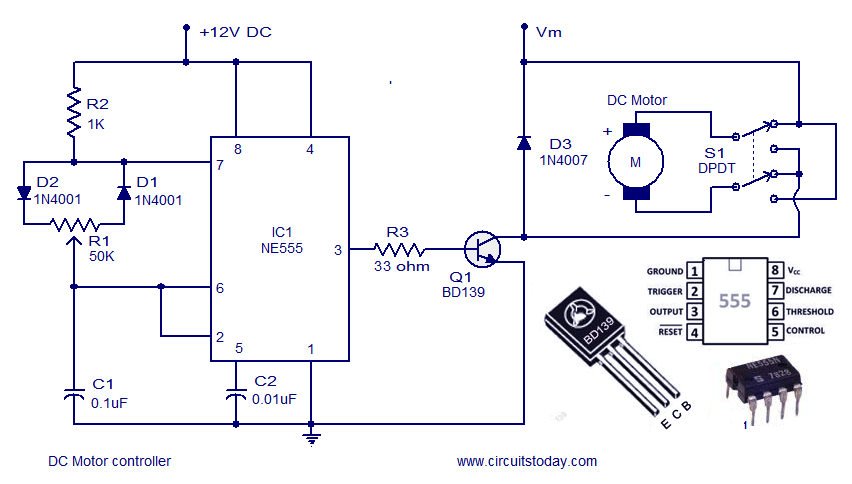
A DC motor controller based on an NE555 timer is presented here. The direction of rotation of the DC motor can also be changed using this DC motor speed control circuit. The described circuit utilizes the NE555 timer IC in...
The circuit consists of the following components: (1) An infrared emitter which utilizes a multi-harmonic oscillator based on a 555 timer circuit. The oscillation frequency is determined by the values of RP1, R1, and C1, resulting in a frequency...
Figure 282 illustrates a simple emergency lamp circuit designed to activate during a power outage. The circuit utilizes a transformer (T) for voltage stepping, diodes (VD1 to VD4) for rectification, and a capacitor (C) for smoothing the output. During...
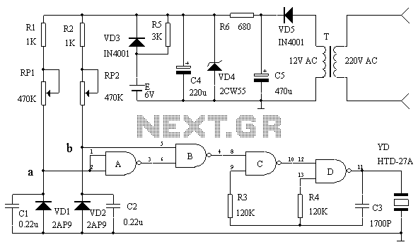
This circuit serves as an over-temperature alarm and cooling system utilizing CD4011 four NAND gate integrated circuits to monitor the oven's temperature. In the event of a thermostat circuit failure or power outage, if the internal temperature exceeds or...
This infrared light valve has more parts, so it works better and more reliable for alarms. The circuit responds less ambient light. The light valve consists of a transmitter and a receiver. The transmitter consists of a NE 555...
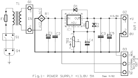
This AC to DC power supply can output 5A in continuous operation and 12A peak current. This type of DC power supply uses a PCB, allowing for two case types for IC1: TO-220 or TO-3. The regulation of this...
Warning: include(partials/cookie-banner.php): Failed to open stream: Permission denied in /var/www/html/nextgr/view-circuit.php on line 713
Warning: include(): Failed opening 'partials/cookie-banner.php' for inclusion (include_path='.:/usr/share/php') in /var/www/html/nextgr/view-circuit.php on line 713