
Masochists Video Card Circuit
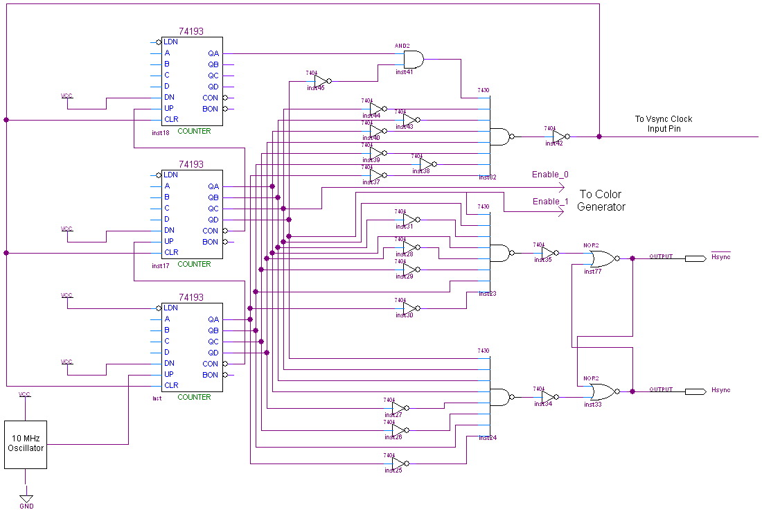
The schematic comprises several critical components that work in conjunction to generate synchronization signals and color outputs for a VGA interface. The Hsync Generator is crucial for generating horizontal synchronization signals, which are essential for displaying images on a monitor. The three 4-bit counters are configured to count clock cycles produced by the 10 MHz oscillator. As the counters increment, they reach specific thresholds that correspond to the timing requirements of the VGA standard.
The 7430 NAND gates play a pivotal role in determining the state of the Hsync signal. When the first counter reaches 210, the Hsync signal is activated, indicating the start of a new horizontal scan line. The subsequent value of 242 is crucial for resetting the signal, ensuring that the display timing remains accurate. The clear signal at 264 resets the counters, allowing for continuous operation without overflow or timing errors.
Hex inverters are strategically placed to maintain a stable logic level at the inputs of the NAND gates, ensuring that the logic conditions for triggering the Hsync signal are met. The use of AND gates is necessary for handling any values that exceed the 8-bit capacity of the 7430, thereby ensuring that the system can accommodate the full range of required values without losing synchronization.
Furthermore, the Color Generator is designed to manage the R/G/B signals effectively. The timing of these signals is critical; they must be enabled only during the appropriate segments of the VGA signal to prevent artifacts or incorrect colors from being displayed. The color enable signals ensure that the color data is only sent when the Hsync and Vsync signals indicate that it is valid to do so, maintaining the integrity of the visual output.
Overall, this schematic integrates various components to achieve a robust VGA signal generation system, ensuring precise timing and accurate color representation on the display.The full schematic for this project is really, really big so if you want to see it, go ahead and click the picture below. Since the schematic is so big I split the explanation of how things are connected together into three sections.
The Hsync Generator, Vsync Generator and Color Generator. The Hsync circuit uses 3x 4-bit counters to count up to specific values that trigger the Hsync signal as well as a clear signal to reset the counter value to 0. A 10 MHz crystal oscillator is input to the first 4-bit counter which counts up. The carry bit from the first counter is connected to the 2nd counter so that the 2nd counter will continue counting upward, likewise for the 3rd counter.
210 (0b11010010), 242 (0b11110010) and 264 (0b100001000) are the three unique values that the 7430 8-input NAND gates are looking for. 210 will trigger the Hsync signal to set to 1, 242 triggers it to reset to 0 and 264 is the clear signal which tells the counters to start counting from 0 again.
Some hex inverters are used to make sure the input into the 7430 NAND gate is "11111111" for each of the specific values we want to trigger Hsync and Clear at. AND gates are used whenever the value is larger than 8 bits, since the 7430 maxes out at 8-bits. Since the R/G/B color output cannot always be active, we need to make sure it is only enabled when the VGA timing allows for color signals to be active.
These two signals are fed into the color generator as color enable signals. 🔗 External reference
Related Circuits

The circuit has four inputs. The voltage gain between each input and the output is maintained at unity by the relative values of the 470 kΩ input resistor and the 470 kΩ feedback resistor. The described circuit operates as a...
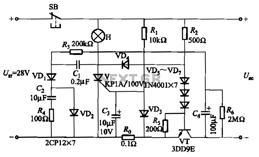
Capacitor C3 is used to determine the cutoff power, specifically the voltage threshold (VT cutoff), which influences the delay time selection. The schematic includes a reset button, SB, that is utilized to reset the system after a failure has...
The camera has been wired with external shutter leads, and a method is needed to trigger them. These leads must be connected together via a relay at regular intervals, approximately every 2 seconds, starting from launch. A 555 timer...

This is a UHF band TV antenna preamplifier circuit with a gain of 15 dB, built using a BF180 UHF transistor. The circuit is straightforward in design. The operational principle consists of two stages. The first stage features a...
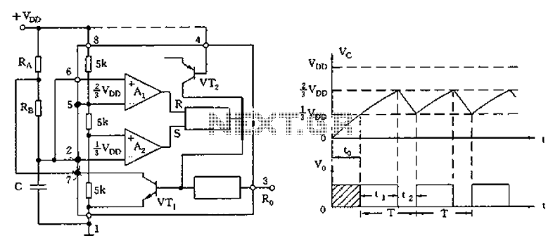
The circuit diagram illustrates the 555 timer (or 556 timer in half configuration) configured in astable multivibrator mode. It features three resistive and capacitive elements connected as shown. In one-shot mode, the trigger terminal (pin 2) is connected to...

This colorful backlit aquarium light provides a natural appearance to the aquarium tank. The aquarium LED lighting circuit automatically turns on at sunset. The aquarium LED lighting system enhances the aesthetic appeal of the aquarium by simulating natural lighting conditions....