
L298N Motor Driver Board Stepper Motor DC Motor Drive
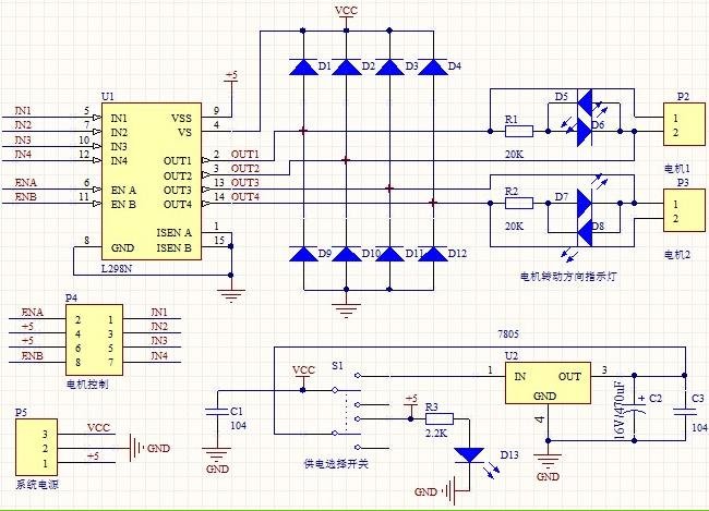
1. Driver: L298N Dual H Bridge DC Motor Driver IC
2. Supply voltage for the driven part (Vs): +5 V to +35 V; for internal board power supply, Vs: +7 V to +35 V
3. Peak current for the driven part (Io): 2A
4. Supply voltage for the logical part (Vss): +5 V to +7 V (can draw power from the board at +5 V)
5. Operating current range for the logical part: 0 to 36 mA
6. Control signal input voltage range:
Low: -0.3 V ≤ Vin ≤ 1.5 V
High: 2.3 V ≤ Vin ≤ Vss
7. Enable signal input voltage range:
Low: -0.3 V ≤ Vin ≤ 1.5 V (control signal inactive)
High: 2.3 V ≤ Vin ≤ Vss (control signal active)
8. Maximum power consumption: 20 W (at temperature T = 75 °C)
9. Storage temperature: -25 °C to +130 °C
10. Driver board dimensions: 55 mm x 49 mm x 33 mm (including fixed copper pillar and heat sink height)
11. Driver board weight: 33 g
12. Additional features: control of direction indicators, logic part power interface.
The L298N Dual H Bridge DC Motor Driver IC is designed to control the direction and speed of DC motors. It operates with a supply voltage (Vs) ranging from +5 V to +35 V, making it suitable for various applications requiring different power levels. For internal board power, the supply voltage must be maintained between +7 V and +35 V. The driver can handle a peak current of 2A, making it capable of driving larger motors.
The logical section of the driver operates with a supply voltage (Vss) between +5 V and +7 V, allowing it to draw power from the board at +5 V. The operating current for the logical part is specified to be between 0 mA and 36 mA, ensuring efficient control without excessive power consumption.
The control signal input voltage has specific thresholds: a low signal is defined as -0.3 V to 1.5 V, while a high signal is defined as 2.3 V to Vss. This allows for a clear distinction between active and inactive states. The enable signal input follows similar voltage ranges, with low signals indicating an inactive control state and high signals activating the control.
The maximum power consumption of the L298N is rated at 20 W when operating at a temperature of 75 °C, indicating its robustness under load. The component is designed to function in a wide temperature range, from -25 °C to +130 °C, making it suitable for various environmental conditions.
The physical dimensions of the driver board are 55 mm in length, 49 mm in width, and 33 mm in height, including the fixed copper pillar and heat sink, which are essential for thermal management. The total weight of the driver board is 33 g, making it a lightweight option for integration into various systems.
Additionally, the L298N provides features for controlling direction indicators and offers a power interface for the logic part of the board, enhancing its versatility in motor control applications. This driver is ideal for robotics, automation systems, and any application requiring precise motor control.1. Driver: L298N Dual H Bridge DC Motor Driver IC 2. Driven part of the terminal supply area Vs: +5 V ~ +35 V; such as the need to take power within the board, the supply area Vs: +7 V ~ +35 V 3. Driven part of the peak current Io: 2A 4. The logical part of the terminal supply area Vss: +5 V ~ +7 V (can take power within the board +5 V) 5.
The logical part of the operating current range: 0 ~ 36mA 6. Control signal input voltage range: Low:-0.3V ≤ Vin ≤ 1.5V High: 2.3V ≤ Vin ≤ Vss 7. Enable signal input voltage range: Low: -0.3 ≤ Vin ≤ 1.5V (control signal is invalid) High: 2.3V ≤ Vin ≤ Vss (control signal active) 8. Maximum power consumption: 20W (when the temperature T = 75 ) 9. Storage temperature: -25 ~ +130 10. Driver Board Size: 55mm * 49mm * 33mm (with fixed copper pillar and the heat sink height) 11. Driver Board Weight: 33g 12. Other Extensions: control of direction indicators, the logic part of the plate to take power interface.
🔗 External reference
Related Circuits
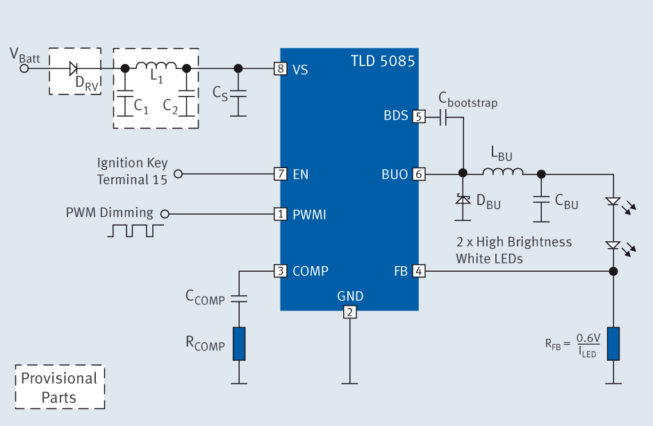
The TLD 5085EJ is a smart LED buck converter featuring an integrated power switch, designed to drive a load current of up to 1.8A with excellent line and load regulation. This device is specifically intended for stepping down input...
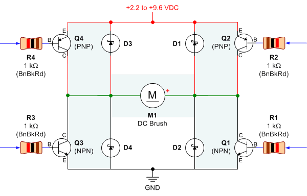
Schematic, breadboard photo, parts list, and results of several transistor variations on the classic bipolar H-bridge motor driver circuit. The classic bipolar H-bridge motor driver circuit is a widely used configuration that allows for the control of DC motors in...
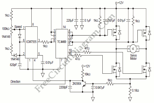
To provide rapid motor speed changes and motor direction reversal, four outputs drive a MOSFET H-bridge. N-channel devices serve as the lower rail power MOSFETs, while P-channel devices are utilized as the upper MOSFETs. All MOSFETs are controlled by...
Many inquiries arise regarding motorcycle wiring, particularly among individuals attempting to repair their blinkers or seeking to streamline electronics for custom builds. A crucial aspect of constructing any chopper, bobber, cafe racer, brat bike, or rat rod involves eliminating...
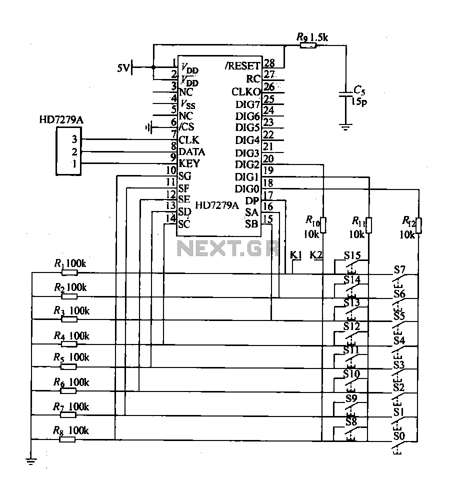
The design includes a front panel featuring buttons for setting 10 number keys (0-9), along with additional keys such as "Move Down," "Health," "Enter," "Recover," and a "Door Key," totaling 16 keys. The system also incorporates an interior door...

These circuits are commonly utilized in robotics to enable DC motors to operate in both forward and reverse directions, as well as to provide an electric brake (short circuit condition). H-bridges can be found as integrated circuits or can...