
Simple Motorcycle Wiring Diagram for Choppers and Cafe Racers
A comprehensive understanding of motorcycle wiring is essential for effective modifications and repairs. The wiring system in motorcycles typically consists of a battery, ignition switch, lighting circuits, and various control switches. The battery serves as the primary power source, supplying voltage to the ignition system and lighting circuits. The ignition switch controls the flow of electricity, allowing the rider to start the motorcycle and activate electrical components.
In the context of custom builds, the wiring harness can be significantly simplified. This involves identifying non-essential components and systematically removing them. It is advisable to maintain essential elements such as the ignition system, headlight, and brake light, as these are critical for safe operation. Wiring diagrams are invaluable tools that provide a visual representation of the electrical system, indicating the connections between various components.
When modifying the wiring harness, it is crucial to follow a methodical approach. Begin by documenting the existing wiring layout, taking note of connections and wire colors. This documentation will serve as a reference during the modification process. Next, carefully remove unnecessary components, ensuring that essential circuits remain intact. Utilize a voltmeter to verify the functionality of components before and after removal.
For riders interested in further simplification, alternative configurations can be explored. For instance, a kickstart-only system can be designed to operate without a traditional battery by integrating capacitors to store and release energy as needed. This requires careful consideration of component ratings and compatibility to ensure reliable operation.
Safety should always be a priority when working with motorcycle wiring. Understanding the implications of removing certain components is vital, as it can affect the overall functionality and safety of the motorcycle. Engaging with the motorcycle community, whether through forums or local groups, can provide valuable insights and support during the modification process.I get a lot of questions about wiring motorcycles. Sometimes people are just trying to fix their blinkers and aren`t familiar with how motorcycle electrics work but more often than not I get requests about trimming down electronics for custom riders. An essential part of building any sort of chopper, bobber, cafe racer, brat bike, or rat rod i s getting rid of all the unnecessary items. These days I just grab my wire snips and start trimming away with no regard for common sense and caution but if you are working with your first wiring loom I`m going to try and give you some guidance right now. If you are trying to build a stripped down bike there is a lot going on that you don`t need. A lot of the controls can be removed, blinkers, gauges and indicators, relays and switches. It doesn`t take a whole lot of wiring to keep a bike on the road, especially if you don`t want to cater to the law word for word.
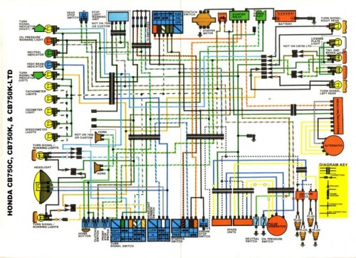
By trimming down the wiring you`ll be saving complexity, saving weight, and cleaning up the look of your bike. Below is a generic wiring diagram I whipped up that can be used as a guideline. I tried not to tailor it specifically to any particular model of bike, and I tried to make it as easy to understand as possible but really any 70`s and early 80`s model bike with carbs will adapt to this diagram quite well.
This diagram is setup to run a headlight and brake light, keep your battery charged, and have a keyed ignition. Personally, I sometimes strip my bikes even further, but I`ll mention that further down the page. When working on your existing wiring loom it is best not to just start cutting wildly (like I do!) but to be very careful.
Inside your headlight is where much of the wiring converges, so is a good place to start. Remove your headlight and start trimming back the sheaths. Slice back the sheaths of the wiring loom as far as possible to expose the wires inside. If this is your first electronics exploration, start with something easier. Pick a fixed item you`d like to remove and trace the wires. An easy starting point is the blinkers. To remove your blinkers, unbolt them one at a time, then trace the wires through the cut open sheath. The grounding wire will most likely be shared with your headlight and gauges depending on the bike, so don`t trace the black wire, just unplug it.
But, you should be able to follow the positive lead from each blinker all the way to the flasher relay which will be near the battery and rectifier under the seat. You can remove all of this wiring, the relay, and of course the blinkers. Keep going one item at a time. You should DEFINITELY be using a volt meter. IF YOU DO NOT HAVE A VOLT METER GO BUY ONE NOW! You can buy a cheap volt meter from Harbor Freight or Northern Tool for around $10 that will look something like this: It will do everything you need.
Or if you are a stickler for high quality tools like I am you can spring for something like a Craftsman Multimeter for around $50-60. This is what I use though I must state, I only use 10% of what this device is capable of. It should be noted that my diagram caters to my desires I generally remove the switch controls on the left side of the handlebars, and the ones on the right if possible (often times the throttle housing and switches are a single unit).
I replace my controls with simple switches picked up from radio-shack, and mount them where ever pleases me at the time. Sometimes I`ll make a little plate to mount them on the dash: Or sometimes I`ll just stick them to the headstock, or under the seat so they are out of the way completely.
The above KZ440 I didn`t remove a lot from. In this picture I had one switch overriding the keyed ignition, and another activating the starter. It was kind of a weird setup, but the only photo I have handy. When removing things you always want to make sure they are either not being utilized or serve no essential purpose. If you have the bike running and you`re watching voltage on a particular item (for example: a neutral switch), you`ll understand when it`s being used and when it isn`t and this will help you make a decision of whether or not it should be cut out.
There is a lot more involved with doing a clean wiring trim than what I`ve mentioned here, but hopefully this helps push you in the right direction. If you have questions, please ask them either here in the comments or on my new Motorcycle Repair Forums.
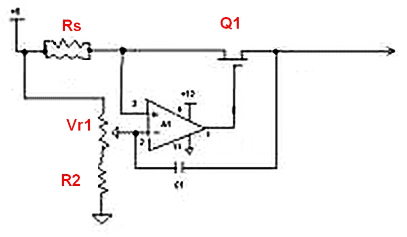
I do my best to help out everyone who posts. Also for some of you who are more adventurous and are looking for a hardcore diagram for modifying a kickstart only bike to run sans battery have a looky: I won`t explain the above right here right now but if you`re looking to go as low profile as possible and have questions, please let me know. On many bikes you`ll need to introduce a capacitor or two and possibly a particular regulator unit. A reader recently had a very note worthy comment. My diagrams above have the brake light controlled by the same switchable power source as the headlight.
This means that you must turn on the headlight for the brake light to be active. While I tend to like this setup it isn`t necessarily the safest. If you forget to turn on your lights, your brake light won`t work. Hans graciously sent me an edited version of my diagram with the adjustment on it. Have a look: 🔗 External reference
Related Circuits
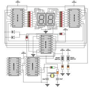
Normally, an analog-to-digital converter (ADC) requires interfacing through a chip to convert analog signals into digital format. This necessitates both hardware and software, resulting in increased complexity and overall cost. The circuit presented here is configured around the ADC...
Assuming a 5V output can be achieved after adjusting the potentiometer, will the 240-ohm resistor limit the current, or is there a need to add additional components? If it does limit the current, it is expected that the power...
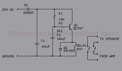
This circuit was designed for an audio amplifier project to control the speaker output relay. The primary function of this circuit is to manage the relay that activates the speaker output in the audio amplifier. The circuit introduces a...
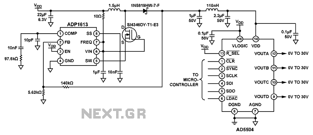
The circuit depicted in FIG. 1 generates a high-voltage signal for controlling the capacitance of barium strontium titanate (BST) capacitors. By applying voltages of V and 3V to the appropriate terminals, the capacitance of the BST can be modified....
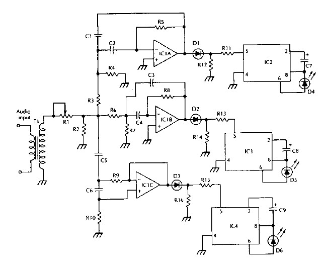
The LM 3909 LED flasher integrated circuit (IC) can be utilized to design various electronic projects. A circuit diagram illustrates the creation of a simple color organ using the LM3909 LED flasher IC. Three active filters process the audio...
The WPG DM8168 DaVinci high-definition video System on Chip (SoC) offers multiple DVR/NVR surveillance solutions, utilizing the MT9M033 image sensor as a key component in safety monitoring systems. This solution is complemented by Conexant's line of multi-channel video surveillance...