
Ultrasonic Beam Barrier Circuit

This ultrasonic intrusion detection circuit is designed to function effectively in various environments, providing a reliable method for monitoring entry points. The use of a 40 kHz frequency ensures that the emitted sound is beyond the audible range for humans, thereby maintaining discretion while still providing effective security.
The transmitter section's oscillator circuit, utilizing BC 548 transistors, is crucial for generating the ultrasonic signal. The precise values of the resistors and capacitors in the oscillator circuit must be carefully selected to ensure that the oscillation frequency is stable and matches the frequency of the ultrasound transmitter. This stability is essential for the receiver to accurately detect the transmitted signal.
In the receiver section, the common emitter amplifier configuration enhances the sensitivity of the system, allowing it to detect even minor disruptions in the ultrasound barrier. The signal detection stage, which includes T2, D1, and C3, plays a vital role in interpreting the amplified signals. When the ultrasound barrier is intact, T3 remains conductive, allowing the system to remain in a low-power state. The transition to alarm mode occurs rapidly when the barrier is breached, demonstrating the system's responsiveness.
The output stage, which includes T4 and the piezo buzzer, is responsible for generating the audible alarm. The red LED serves a dual purpose: it indicates that the system is armed and provides visual feedback to users regarding the operational status of the circuit. This combination of visual and auditory signals enhances the effectiveness of the intrusion detection system, making it a valuable tool for security applications.
Overall, this circuit exemplifies a practical application of ultrasonic technology in security systems, showcasing the integration of electronic components to create a functional and efficient barrier detection mechanism.This circuit generates inaudible ultrasound to make a barrier across the entry. At the moment the circuit detects a break in the sound barrier, it generates a loud alarm indicating the entry of a person. This can be used to protects the entry passages and helps to detect unauthorized entry of persons in protected areas.
The circuit has two section s. An Ultrasound transmitter and a receiver. Both the circuits use 40 kHz Ultrasound transmitter (TX) and ultrasound receiver (RX) pair to transmit and receive the ultrasound. The Transmitter section uses the ultrasound transmitter TX in conjunction with an emitter coupled oscillator comprising T1 and T2, both BC 548.
The values of resistors and capacitors determine the oscillation at 40 kHz frequency which exactly matches with that of the transmitter. The receiver section has a 40 kHz ultrasound receiver RX which is connected to the base of T1. It is a common emitter amplifier which amplifies the signals received by the RX. The amplified signal available from the collector of T1 is coupled via C2 to the signal detector stage comprising T2, D1 and C3.
When RX continuously receives the ultrasound from TX, T3 remains saturated and conducts. This keeps T4 output conduction since its base is at ground potential. When the ultrasound beam breaks, T3 turns off and T4 conducts. The piezo buzzer connected to the collector of T4 sounds the alarm. Red LED indicates the standby mode showing that the alarm system is active. 🔗 External reference
Related Circuits
A popular project among microcontroller enthusiasts is to build a radio-controlled clock. Tiny receiver boards are available, equipped with a pre-tuned ferrite antenna that receives and demodulates the DCF77 time signal broadcast from Mainflingen in Germany. DCF77 has an...
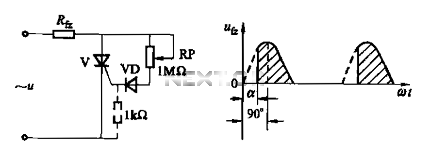
Figure 16-3 (a) illustrates a one-way thyristor, while Figure 16-3 (c) depicts a triac. The circuit characteristics indicate a simple phase shift range of 90 degrees for the thyristor and 180 degrees for the triac. These components are influenced...
The following circuit illustrates a Repeating Interval Timer Circuit Diagram. This circuit is based on the CMOS 4060 integrated circuit (IC). Features include a 6-pin output. The Repeating Interval Timer Circuit utilizing the CMOS 4060 IC is designed to generate...
This is a compact, easy-to-build amplifier that utilizes a single integrated circuit (IC) to deliver 40 watts of audio power. It is well-suited for amplifying audio signals from devices such as mobile CD players or iPods. The integrated circuit...
Charging the battery in a slow manner (using a low charging current over an extended period) is the most economical and safest method. The design of the trickle charger should focus on two key points: firstly, the use of...
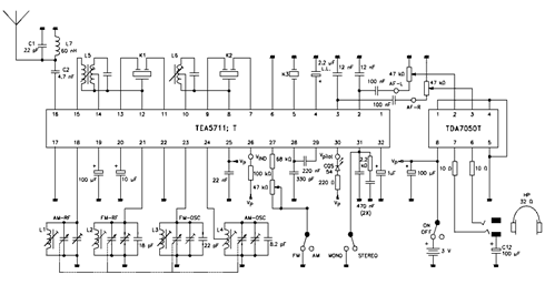
The TEA5711 datasheet indicates that essential functions, including the AM and FM front end, AM detector, and FM stereo output stages, are integrated within the TEA5711 AM/FM stereo radio circuit. The accompanying circuit diagram illustrates the TEA5711T in conjunction...