
Lamp Fader schematic
The described sunset lamp operates on a 12 Volt power supply, utilizing a 25 Watt incandescent or LED lamp. The circuit is designed to provide an automatic dimming feature, simulating a natural sunset effect.
The core of the circuit likely includes a microcontroller or a timer circuit that manages the brightness of the lamp. Upon activation, the circuit powers the lamp at full brightness. The dimming process can be achieved through pulse-width modulation (PWM) or by using a variable resistor in conjunction with a transistor to gradually decrease the current flowing to the lamp over a period of 1.5 hours.
To implement this, a relay or a MOSFET may be utilized to control the power to the lamp, allowing for smooth transitions in brightness. The microcontroller can be programmed to decrease the duty cycle of the PWM signal or adjust the resistance in the circuit gradually over the specified time frame.
After the sunset effect is completed, the lamp remains off until the power is recycled, which can be managed through a simple switch or a timer that resets the microcontroller. The entire circuit should be designed with appropriate heat dissipation methods, especially if using incandescent lamps, to ensure safety and longevity of the components.
Additionally, capacitors may be included in the circuit to smooth out any voltage fluctuations and ensure stable operation, while resistors can be used to limit current and protect sensitive components. Overall, this design provides a simple yet effective way to create a relaxing ambiance by mimicking the natural fading of sunset light.The sunset lamp comes on at full brightness and then slowly fades out over 1.5 hours time and stays off until power is recycled. You can use 12 Volt 25 Watt lamps. 🔗 External reference
Related Circuits
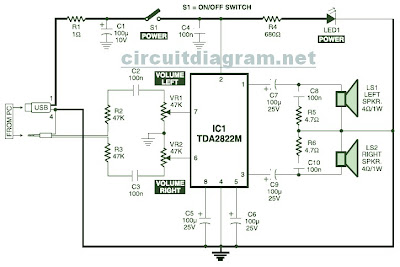
This is the circuit diagram of a USB-powered computer speaker, commonly referred to as multimedia speakers for PCs. The circuit features a single-chip design, operates on a low-voltage electrical power supply, is compatible with USB power from computers, includes...
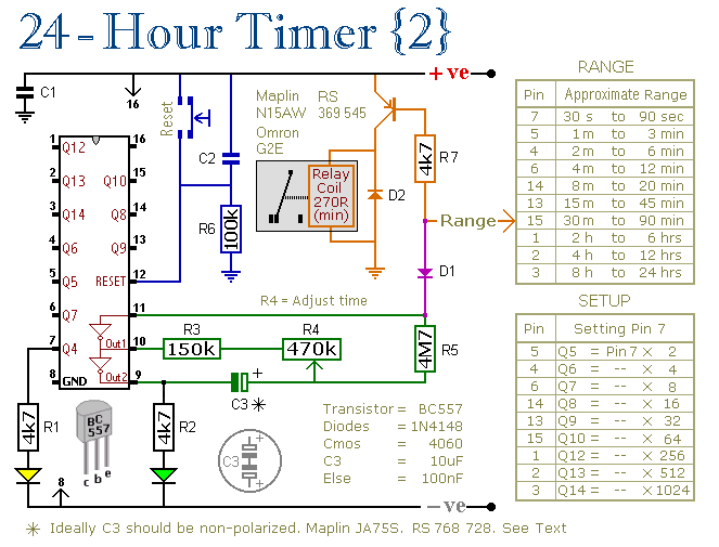
These two circuits are multi-range timers that offer periods of up to 24 hours and beyond. They can function as repeating timers or single-shot timers. Both circuits are fundamentally the same, with the primary distinction being their behavior in...
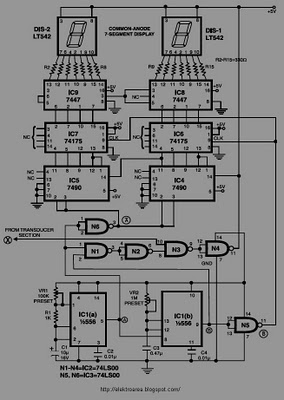
This circuit is designed to display the speed of a vehicle in kilometers per hour (km/h). An opaque disc is mounted on the spindle connected to the front wheel of the vehicle. The disc features evenly spaced holes along...
There are at least three different versions of this circuit. The first DM-2 version utilized the MN3005 BBD and the MN3101 Clock Driver IC (PCB marking: ET5214-510). Later, the clock driver was changed to the MN3102, and the BBD...
With this tester you can check whether a diode is working properly. In the table you can see what LED to indicate the positions of the switch and condition of the diode. The circuit can be connected to a...

Electronic FM Telephone Transmitter Schematic. The following schematic design illustrates a circuit diagram for an FM telephone transmitter built on a compact PC board layout. This small design allows it to be easily integrated within the housing of a...