
Lamp pulser circuit
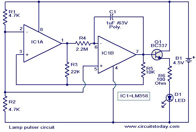
The circuit utilizes the LM358 dual op-amp IC, which contains two independent, high-gain, frequency-compensated operational amplifiers. The configuration for generating the triangular wave involves connecting one op-amp as a comparator and the other as a feedback oscillator. The output of the first op-amp is fed back to the inverting input of the second op-amp, which, along with the timing components R4 and C1, determines the frequency and duty cycle of the triangular waveform.
The selected values for R4 and C1 are critical for achieving the desired timing of approximately 5 seconds. The resistor R4 controls the charge and discharge rates of capacitor C1, which, in turn, establishes the timing for the LED or lamp to gradually brighten and dim. The BC337 transistor serves as a switch, allowing the circuit to control the current flowing through the load. When the output from the op-amps reaches a certain threshold, the transistor is activated, allowing current to flow and illuminating the LED or lamp.
This gradual pulsing effect can enhance the aesthetic appeal of various decorative setups, such as holiday lighting or ambient lighting in different environments. The simplicity of the circuit and the availability of the components make it an accessible project for both hobbyists and professionals interested in creating dynamic light displays.Here is a simple circuit that can be used to pulse an LED or a low power filament lamp. The effect is such that the LED lights up from OFF state gradually and then dims gradually. Such a circuit is very useful in decoration purposes. The circuit is nothing but a triangular wave generator based on dual opamp IC LM 358. The two opamps inside the IC i s used for the purpose. The transistor Q1 BC337 is used to drive the load (LED or lamp). The resistor R4 and capacitor C1 are the timing components of the circuit. Here the values of R4 & C1 are so chosen that the timing is around 5S. 🔗 External reference
Related Circuits

The circuit is designed to connect in parallel with a telephone, displaying the dialed number using DTMF (Dual Tone Multi-Frequency) signaling. It can also show the number dialed from the receiving party's phone, making it useful for capturing numbers...
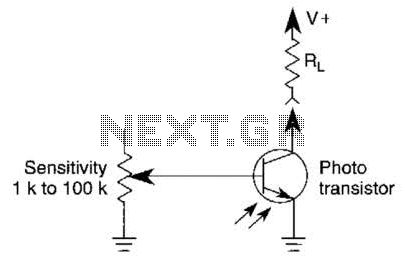
A variable resistor is utilized to adjust the light-level response of a phototransistor. Phototransistors exhibit higher light sensitivity compared to photodiodes; however, they typically demonstrate a lower frequency response. A variable resistor, often referred to as a potentiometer or rheostat,...

A DC power supply can be designed using high voltage transistors to provide an adjustable supply voltage ranging from 10 to 300 volts, which can be modified with potentiometer P1. Transformers used in these power supplies typically feature multiple...

This is a digital calendar circuit that utilizes a microcontroller to display the date, day, and month on an LED display. The entire system is managed by an 8-bit microcontroller, which operates based on a program embedded in its...

At dawn, light illuminates the photosensitive resistor RL, causing its resistance to decrease. This switch IC (2) exhibits a high electrical footprint. When light is present, the relay K does not activate. At night, in the absence of light,...
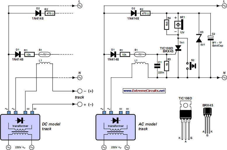
Short circuits in the tracks, points, or wiring are almost inevitable when building or operating a model railway. Although transformers for model systems must be protected against short circuits by built-in bimetallic switches, the response time of such switches...