
Laser Alarm

The laser alarm system operates on the principle of light interruption and voltage comparison to detect unauthorized access. The TL072 op-amp serves as the core component, functioning as a comparator to differentiate between the reference voltage and the voltage generated by the photodiode. When the beam is intact, the voltage at the inverting input (pin 2) remains higher than the non-inverting input (pin 3), keeping the output low. Upon interruption, the inverting input voltage drops, triggering a high output state that can activate alarm devices.
The adjustable voltage divider (P1/R4) allows for calibration of the system to account for varying ambient light conditions, ensuring reliable operation. Hysteresis introduced by R2 is crucial for stabilizing the output state, preventing false alarms caused by minor fluctuations in light levels. The capacitor (C1) not only filters out noise but also introduces a delay, allowing for brief interruptions without triggering the alarm, which is particularly useful in environments where small animals or moving objects might cross the beam.
The design emphasizes simplicity and ease of assembly, making it accessible for hobbyists and professionals alike. The use of mirrors enhances versatility, allowing the system to be configured for various environments, whether it be a doorway or a specific area within a space. Furthermore, the enclosure design minimizes the risk of tampering while ensuring optimal performance. The integration of a black drinking straw at the entry point of the sensor effectively narrows the sensitivity to only the intended laser beam, thereby enhancing the system's robustness against false triggers from ambient light. Overall, this laser alarm system exemplifies an effective and innovative approach to security applications, combining straightforward electronics with practical design considerations.This circuit is a laser alarm system like the one we see in various movies. It uses a laser pointer beam to secure your valuables and property. Essentially, when the beam gets interrupted by a person, animal or object, the resistance of a photodiode will increase and an alarm will be activated. The laser and the receiver can be fitted in same box, sharing a common power supply. As the receiver draws less than 10 mA on average, you`ll soon find that the laser is the most current hungry device! Mirrors are used to direct the beam in whatever setup you require. Examples of a passage and an area protected by the alarm are shown in the diagram. In the circuit diagram we find a TL072 op-amp (IC1. A) configured as voltage comparator between the voltage reference provided by the adjustable voltage divider P1/R4 and the light-dependent voltage provided by the voltage divider consisting of photodiode D1 and fixed resistor R3.
When the laser beam is interrupted, the voltage on comparator pin 2 drops below that at pin 3, causing the output to swing to (almost) the positive supply voltage and indicating an alarm condition. This signal can drive a siren, a computer or a light that hopefully will deter the intruder. Alternatively it can be used to silently` trigger a more sophisticated alarm. Resistor R2 provides some hysteresis to prevent oscillation when the two comparator input voltages are almost equal.
Capacitor C1 makes the circuit immune to short, accidental interruptions of the beam, e. g. , by flying insects. If you want your circuit to have faster responses you can reduce its value to 1 µF. The operation of the circuit is illustrated by the waveform diagram, which also proves the hysteresis action that sets an upper and a lower threshold on the input voltage. You can also see the delay introduced by capacitor C1. The circuit is simple and could be assembled on a piece of breadboard. After assembling the circuit and testing it, you should mount it in a black box that has just a small hole.
You may decide to put the laser in the same box but only if you are sure there is no way the photodiode can see` the laser beam directly. The small hole should be filled with a black drinking straw so that only light from the direction of the laser beam can enter.
With the appropriate setup of the box and the mirrors, the laser beam is so intense that even direct sunlight cannot affect the operation of the photodiode. 🔗 External reference
Related Circuits
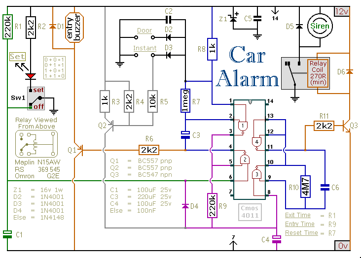
This car alarm circuit includes exit and entry delays, an instant alarm zone, an intermittent siren output, and automatic reset. By incorporating external relays, it is possible to immobilize the vehicle and activate the flashing lights. The car alarm circuit...

Abstract Can you recall the movie Entrapment, in which the lead actress, Katherine Zeta-Jones, attempted to bypass the security systems of a building to obtain a highly valuable item? In the film, she had to train extensively to navigate...

This automatic door opener can be constructed using readily available components. The electromagnetic relay at the output of this device can be utilized to control the door mechanism. The automatic door opener circuit is designed to facilitate the opening of...
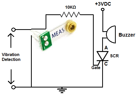
This alarm is designed for use in a room or area that should typically remain motionless. In an environment devoid of movement, no vibrations will be detected, and the alarm will remain inactive. However, once the circuit identifies a...

The circuit automatically activates when the car is turned off, providing a variable time for the user to exit and secure the vehicle. It also offers a variable time delay for entering and starting the car. The 555 oscillator/timers...
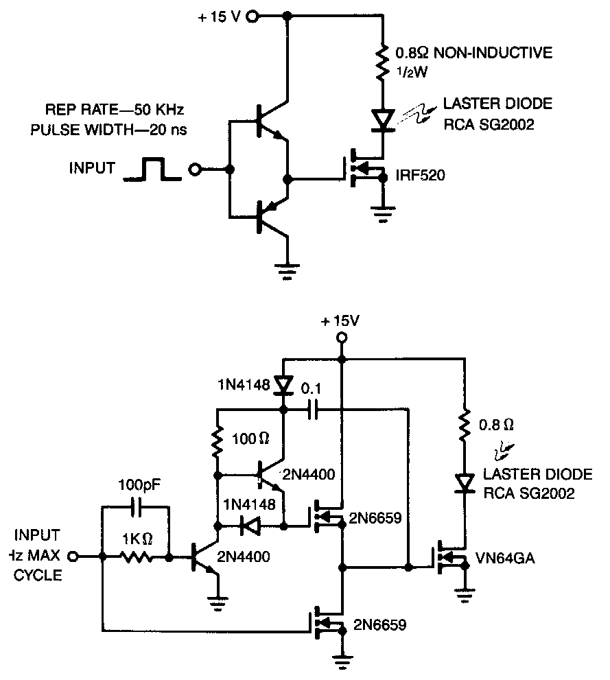
The laser diode pulser is a simple drive circuit capable of driving the laser diode with 10 A, 20 ns pulses. For a 0.1% duty cycle, the repetition rate will be 50 kHz. A complementary emitter follower is used...