
Laser Communication (Transmitter & Receiver)
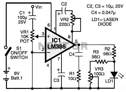
The laser communication system operates by converting audio signals into light signals and vice versa. The transmitter consists of a laser diode that modulates its light output based on the audio signal input. The audio signal, sourced from devices like CD or DVD players, is first conditioned by the LM386 amplifier, which boosts the signal level to drive the laser diode effectively. The laser diode's output is then directed towards a solar panel, which serves as the receiver in this system.
When the laser beam hits the solar panel, it generates a small voltage proportional to the intensity of the received light. This voltage is subsequently amplified by a second LM386 circuit (IC2), which is configured to ensure optimal audio reproduction through the connected speaker. The use of capacitors in the circuit, such as C5 and C7, is crucial for filtering and stabilizing the signals, ensuring that only the intended audio frequencies are amplified while DC offsets are removed.
The design illustrates a simple yet effective method of wireless audio transmission, leveraging the properties of light for communication. The circuit's reliance on commonly available components, such as the LM386 and standard resistors and capacitors, makes it accessible for experimentation and educational purposes. However, safety precautions must be taken when working with laser components to prevent any potential eye damage.This is the circuit diagram of laser communication system that transmit the sound or music signals by way of a laser beam. The intensity of the laser beam varies together with the amplitude of the sound signal. The variation within the inte This is the circuit diagram of laser communication system that transmit the sound or music signals b
y way of a laser beam. The intensity of the laser beam varies together with the amplitude of the sound signal. The variation within the intensity of the laser beam is converted into a variation in the voltage level by utilizing a calculator`s solar panel. The voltage variation on the solar panel is amplified by a low-voltage audio power amplifier LM386 and reproduced by a speaker.
The maximum output of audio amplifier LM386 is 1W, whilst its voltage achieve is 20 to 200. The circuit module consists of a transmitter and also a receiver. Either the transmitter as well as the receiver are assembled around IC LM386, it is powered by a 9V battery. Take a note that this circuit is different with AV transmitter and AV receiver which can be used for sound and video communication, this laser communication circuit only work for audio/sound transmission.
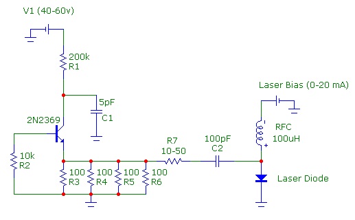
A laser diode (LD1) with maximum operating voltage of about 2. 6V DC and maximum operating current of 45 mA is applied to transmit the audio signal. The voltage divider network formed by R2, R3 and VR3 keeps the voltage and also the current for the laser diode in the secured spot. In place of the laser diode, it is possible to also use a laser pointer. Take out the battery from the laser pointer. Extend two wires from terminals of LD1 and connect them towards the battery terminals of laser pointer.
The spring within the laser pointer will be the negative terminal. The output power of the laser pointer is 5 mW. Be careful when doing work with laser, as direct exposure to the laser beam could be hazardous to your eyes. Point the laser beam to the solar panel. Potmeter VR1 (10-kilo-ohm) is applied to adjust the level of the input audio signal. The audio input (Vin) is taken from the preamplifier output of the music system (CD player, DVD player, etc).
Capacitor C2 and preset VR2 are applied to vary the gain of the LM386. The audio signal transmitted by the laser diode (LD1) is received by the calculator`s solar panel and amplified by IC2. The gain of the amplifier is fixed by capacitor C7. Preset VR4 is utilized to adjust the signal level from the solar panel. This signal is fed to input pin 3 of IC2 via coupling capacitor C5 so that the DC value from the solar panel could be eliminated.
The amplified output from IC2 is fed towards the speaker, which plays the music from the CD player linked on the input (Vin) of IC1. 🔗 External reference
Related Circuits
Building a DIY Alarm System: The Concept. An alarm system serves to protect property, whether it be a room, vehicle, or outdoor area. The primary function of the alarm system is to alert the designated administrator of any intrusion...
A faster driver can supply a higher peak gate current to switch the VN64GA very quickly. The circuit uses a VMOS totem pole stage to drive the high power switch. The described circuit employs a VMOS (Vertical Metal Oxide Semiconductor)...
Continuous wave (CW) operation is achievable with a current of up to 350 mA from a supply voltage range of 2 to 6 V. The system supports TTL modulation frequencies of up to 10 kHz, with an adjustable duty...
The speed of light has been measured using various ingenious methods. This note describes a conceptually simple and relatively easy-to-implement technique known as the time-of-flight optical pulse delay method. It utilizes a short (nanosecond) optical pulse and an oscilloscope...
A home intercom system can be constructed using a versatile circuit design. This system allows communication across up to ten different locations or rooms discreetly. It utilizes a single changeover switch for selecting the desired location, replacing the traditional...
Due to the high frequency of light within the electromagnetic spectrum, it serves as a superior medium for communication compared to radio waves. Lasers are ideal for communication links because they produce a powerful and narrow beam that is...
Warning: include(partials/cookie-banner.php): Failed to open stream: Permission denied in /var/www/html/nextgr/view-circuit.php on line 713
Warning: include(): Failed opening 'partials/cookie-banner.php' for inclusion (include_path='.:/usr/share/php') in /var/www/html/nextgr/view-circuit.php on line 713