
Free-Air Laser Light Communications
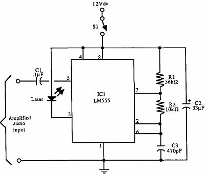
Laser light communication systems leverage the unique properties of lasers to transmit information over distances with minimal interference. The system typically consists of a laser diode that acts as the transmitter, converting electrical signals into light signals. These signals can be modulated using techniques such as amplitude modulation (AM), frequency modulation (FM), or pulse modulation. The choice of modulation technique depends on the application requirements, such as distance and data rate.
On the receiving end, a photodetector, typically a photodiode, captures the incoming light signals and converts them back into electrical signals. The design of the optical path is crucial, as it must ensure that the laser beam remains focused and directed toward the photodetector, minimizing losses due to divergence. Collimating lenses may be employed to maintain beam quality over long distances.
In practical applications, laser light communication systems can be used for point-to-point communication links, such as in free-space optical communication, where the laser beam travels through the atmosphere. This technology is particularly advantageous in environments where traditional wired communication may be impractical or too costly.
Overall, the development and implementation of laser light communication systems represent a significant advancement in the field of telecommunications, offering high data rates and secure transmission capabilities. As technology progresses, it is anticipated that the limitations currently faced in utilizing the full spectrum of light for communication will be addressed, unlocking new possibilities for data transmission and connectivity.Because light is at such a high frequency in the electromagnetic spectrum, it`s an even better medium for communications than radio waves. Lasers are perfect instruments for communications links because they emit a powerful, slender beam that`s least affected by interference and is nearly impossible to intercept.
This section explains the basics o f laser light communications using both helium- neon and semiconductor lasers. You`ll discover the different ways light can be modulated and cajoled into carrying an analog signal from a microphone or FM radio. The following section details advanced projects in laser light communications. Higher frequencies in the radio spectrum provide greater bandwidth. The bandwidth is the space between the upper and lower frequencies that define an information channel.
Bandwidth is small for low-frequency applications such as AM radio broadcasts, which span a range 540 kHz to 1600 kHz. That`s little more than 1 MHz of bandwidth, so if there are 20 stations on the dial, that`s only 50 kHz per deejay.
Television broadcasts, including both VHF and UHF channels, span a range from 54 MHz to 890 MHz, with each channel taking up 6 MHz. Note that the 6 MHz bandwidth of the TV channel provides more than 100 times more room for information than the AM radio band.
That way, television can pack more data into the transmission. Microwave links, which operate in the gigahertz (billions of cycles per second) region, are used by communications and telephone companies to beam thousands of phone calls in one transmission. Many calls are compacted into the single microwave channel because the bandwidth required for one phone conversation is small compared to the overall bandwidth provided by the microwave link.
Visible light and near-infrared radiation has a frequency of between about 430 to 750 terahertz (THz) ”or 430 to 750 trillion cycles per second. Thanks to the immense bandwidth of the spectrum at these high frequencies, one light beam can simultaneously carry all the phone calls made in the United States, or almost 100 million TV channels.
Of course, what to put on those channels is another thing! Alas, all of this is theoretical. Transmitters and receivers don`t yet exist that can pack data into the entire light spectrum; the current state of the art cannot place intelligent information at frequencies higher than about 25 or 35 gigahertz (billion cycles per second). It might take a while for technology to advance to a point where the full potential of light beam communications can be realized.
Even with these limitations, light transmission offers additional advantages over conventional techniques. Light isn`t as susceptible to interference from other transmissions, and when squeezed into the arrow-thin beam of a laser, is highly directional.
It is difficult to intercept a light beam transmission without the intended receiver knowing about it. And, unlike radio gear, experimenting with even high-power light links does not require approval from the Federal Communications Commission.
Businesses, universities, and individuals can test lightwave communications systems without the worry of upsetting every television set, radio, and CB in the neighborhood (however, CDRH regulations must be followed). On the down side, light is greatly affected by weather conditions, and unlike low frequencies such as AM radio, it does not readily bounce off objects.
Radar (low-band microwave) pierces through most any weather and bounces off just about everything. It`s easy to see how laser lightwave communication links work by first experimenting with a system designed around the common and affordable visible light-emitting diode. The LED provides a visual indication that the system is working and allows you to see the effects of collimating and focusing optics.
The LED communications link, like any other, consists of a transmitter and receiver. An LED is used as the 🔗 External reference
Related Circuits
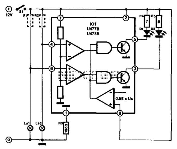
This circuit is designed for monitoring automotive lighting. Two specialized integrated circuits (ICs) from Telefunken are used to measure the current through a light bulb. Detecting whether current flows through a bulb is an effective method to determine its...
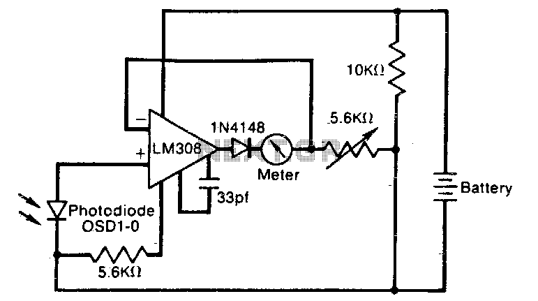
The meter reading is directly proportional to the logarithm of the input light power. The logarithmic circuit behavior arises from the nonlinear diode p-n junction current/voltage relationship. The diode in the amplifier output prevents the output voltage from becoming...
This circuit features a white LED-based emergency light that provides several benefits. It is exceptionally bright due to the incorporation of white LEDs. The light activates automatically when the mains supply is interrupted and deactivates when mains power is...
Hobby servos convert DMX signals into mechanical motion. Typically, hobby servos require a pulse with a variable width ranging from 1 to 2 milliseconds, with 1.5 milliseconds representing the center position. The schematic below illustrates a simple voltage-to-pulse-width circuit....
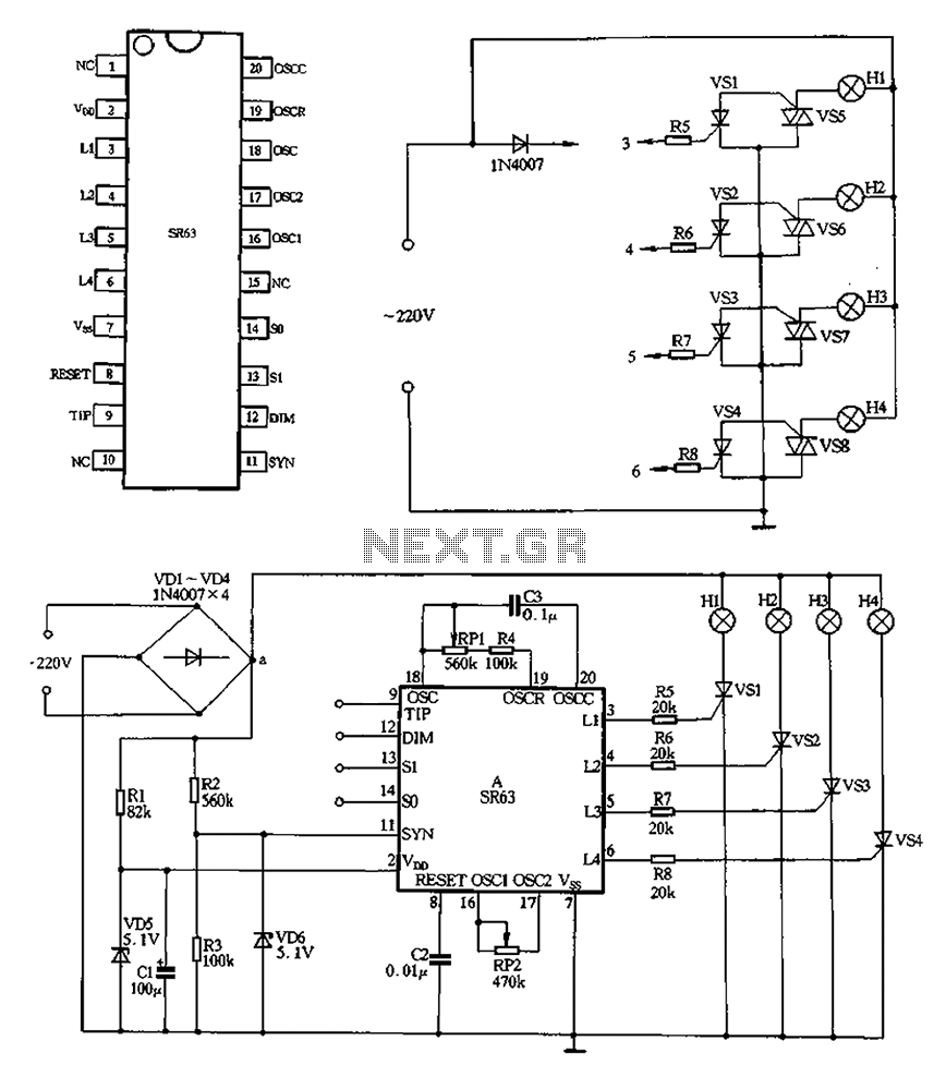
220V AC is converted to DC after passing through a VDI ~ VD4 bridge rectifier. The output from one point supplies power directly to lights H1 through H4. Another route passes through R1, a buck converter, and VD5, which...
This circuit effectively simulates various light sources such as a house fire, campfire, or welding light without the use of a microcontroller, although it requires a considerable number of components, including some uncommon ones. It is based on three...