
Laser diode pulser

The described drive circuit is designed to control a laser diode effectively, delivering high current pulses essential for applications requiring rapid on-off switching. The capability to provide 10 amperes of current in 20 ns pulses indicates a robust design suitable for high-power laser applications, such as in industrial cutting or medical devices.
The complementary emitter-follower configuration enhances the drive capability by providing high current gain while maintaining a low output impedance. This configuration allows the circuit to drive the laser diode efficiently, ensuring that the diode receives the necessary current without significant voltage drop across the driver stage.
The specification of a 0% duty cycle at a 50 kHz repetition rate suggests that the laser operates in a pulsed mode, which is critical for preventing overheating and extending the lifespan of the diode. The drive circuit's ability to achieve this high frequency is contingent upon the switching speed of the bipolar transistors used. The frequency response of these transistors must be optimized to minimize delays and ensure that the pulses are delivered accurately and consistently.
Additionally, the impedance of the drive source plays a crucial role in the overall performance of the circuit. A lower impedance can enhance the speed of the current rise and fall times, thus improving the overall efficiency of the drive. Careful selection of components, including the transistors and associated passive elements, is essential to achieve the desired performance metrics.
In summary, the drive circuit's design allows for effective control of a laser diode through high-speed pulsing, ensuring that it meets the rigorous demands of various applications while maintaining reliability and efficiency.This drive is capable of driving the laser diode with 10 ampere, 20 ns pulses. For a 0% duty cycle, the repetition rate will be 50 kHz. A complementary emitter-follower is used as a driver Switching speed is determined by the fr of the bipolar transistors used and the impedance of the drive source.
Related Circuits
It has been observed that the receiver performed poorly when positioned at the center of the brightest spot of the reflected laser beam compared to when it was placed off-centered. This suggests that the circuit may have been saturated...
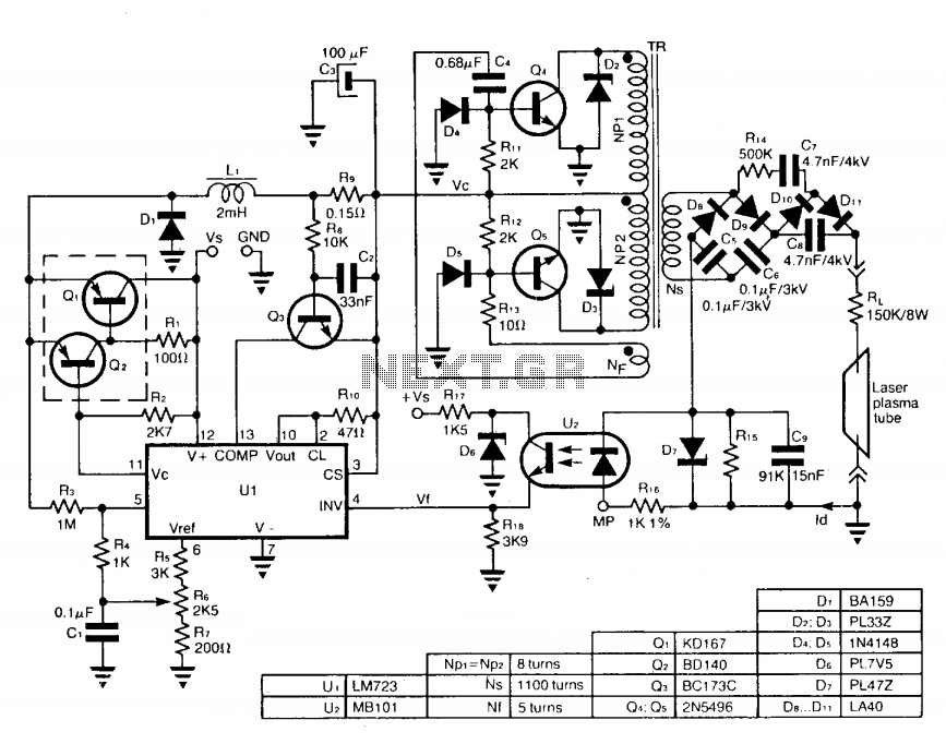
The circuit employs a free-running push-pull DC to DC high voltage converter to generate the required voltage for the laser plasma tube supply. The supply voltage (Vc) of this converter is regulated by a switch-mode power supply to maintain...
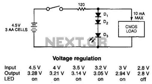
The simple diode network can stabilize the voltage supplied to CMOS circuitry from a battery. D1 and D2 must have a combined forward-voltage drop of about 1.5 V. D3 is an LED with a forward-voltage drop of about 1.7...
The previous section discussed several basic free-air laser light communication projects. It covered the modulation of a He-Ne laser beam using a transformer, transistor, and a piece of Mylar foil stretched in a needlepoint hoop. Various methods for electronically...
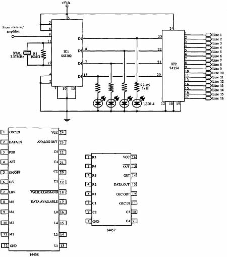
This set of two circuits forms the basis for a very simple light wave transmitter. A LASER beam is modulated and then aimed at a receiver that demodulates the signal and then presents the information (voice, data, etc.). The...
The circuit utilizes two white LEDs, with the second LED connected across the emitter of the transistor and the negative ground. It requires its own limiting resistor in series, similar to R15 and D3 in the circuit diagram. If...