
Stabilizing a laser discharge current
Due to the high operating frequency of the high voltage converter (25 kHz), the ripple in the laser output power is less than 2 x 10^-4. The stability of the discharge current (ID) is better than 10^-2 for variations in supply voltage (Vs) within a range of ±10%, and it is influenced by the sensitivity of the optoisolator.
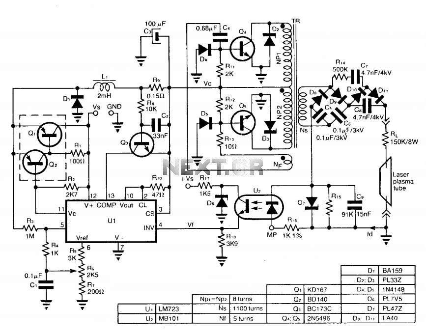
The circuit design incorporates a free-running push-pull configuration for the DC to DC high voltage converter, which is essential for generating the high voltage necessary for the laser plasma tube. The switch-mode power supply plays a critical role in adjusting the supply voltage (Vc) to ensure that the load current remains stable, which is crucial for consistent laser performance.
The opto-electronic isolator (U2) serves to provide electrical isolation between the high voltage components and the control circuitry. By measuring the discharge current (ID) across resistor R18, the circuit can accurately monitor the performance of the laser plasma tube. The proportional voltage (Vp) generated by the optoisolator allows for precise control of the operational amplifier (U1), which in turn regulates the output based on the feedback received from the opto-isolator.
Protection components such as diode D7 and resistor R15 are strategically placed to safeguard the optoisolator from potential damage due to high-voltage spikes during the ignition process, ensuring the longevity and reliability of the circuit.
The high operating frequency of 25 kHz minimizes the ripple in the output power of the laser, which is critical for applications requiring stable and consistent performance. The circuit's ability to maintain a discharge current stability of better than 10^-2 under varying supply voltage conditions indicates a robust design that can accommodate fluctuations in input power while still delivering reliable output. The sensitivity of the optoisolator further enhances the circuit's performance, allowing for fine-tuning and adjustments as necessary to maintain optimal operation of the laser plasma tube.The circuit uses a free-running push-pull dc to dc high voltage converter to get the necessary voltage for the laser plasma tube supply. The supply voltage Vc of this converter, is adjusted by a switch-mode power supply in order to keep the load current constant, at set value.
The linear opto-electronic isolator U2, connected in series with the laser plasma tube, gives a voltage Vp proportional to the discharge current ID across R18, having the correct polarity to drive directly the inverting input of Ul, D7, R15 protects the optoisolator diode against damage produced by the high voltage ignition pulse. Due to the high operating frequency of the high voltage converter (25 kHz) the ripple of the laser output power is less than 2.10~4. The stability of ID is better than 10~2, for variations of supply voltage Vs is the range of ± 10%, and depends on the optoisolator sensitivity.
🔗 External reference
Related Circuits
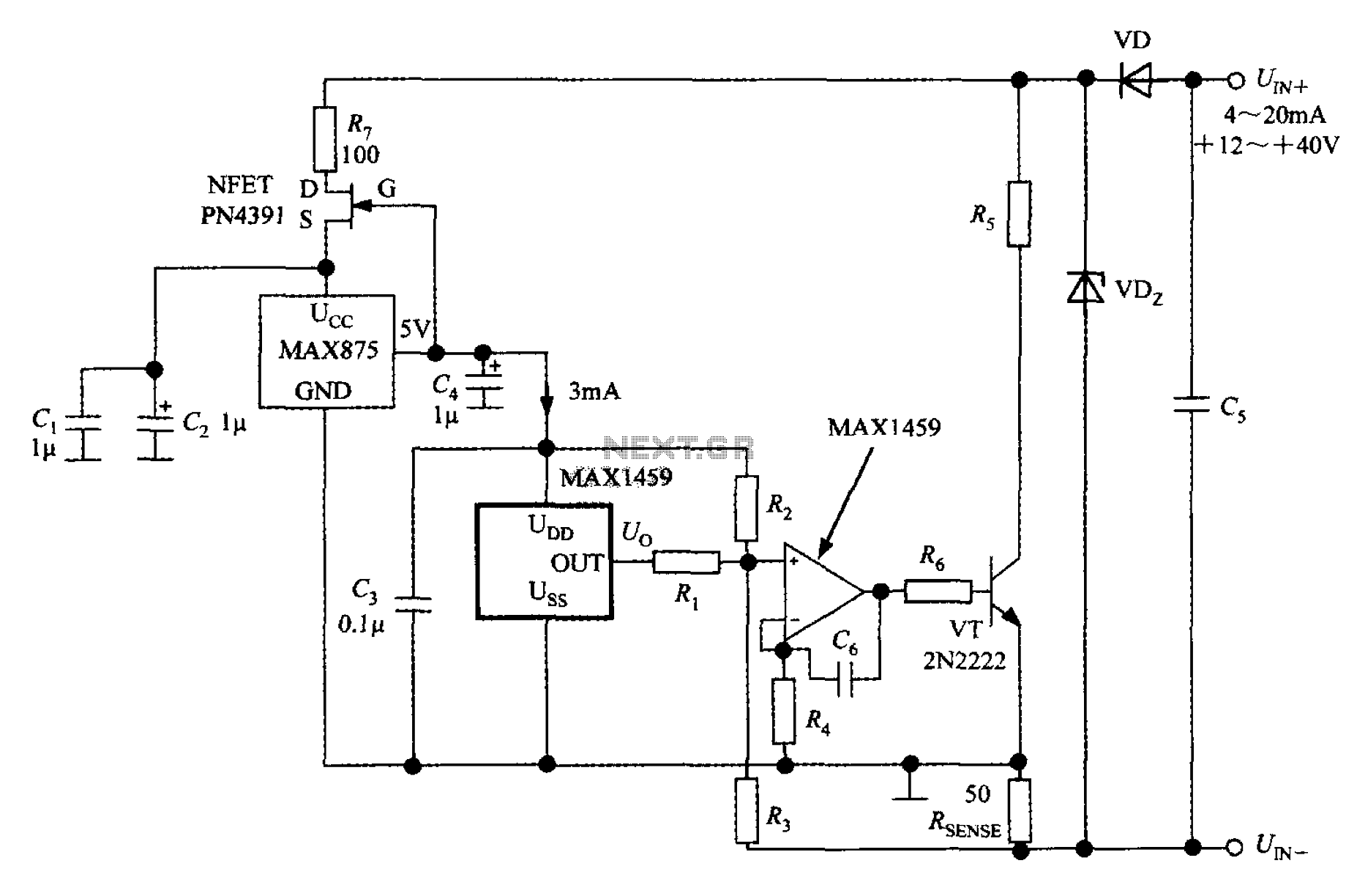
A 4 to 20 mA current transmitter circuit is implemented using the MAX1459, as illustrated in the accompanying figure. The output voltage from the programmable gain amplifier (PGA) is supplied to a spare amplifier chip, and subsequently, an external...
The current source in the diagram reacts very quickly to changes in the input signal and may be utilized in specific measurements. Differential. The current source depicted in the schematic is designed to provide a stable output current that responds...
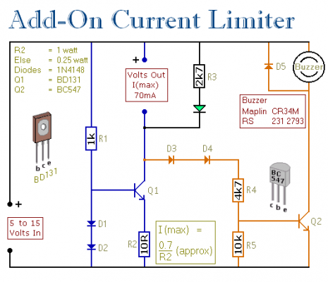
This circuit enables the user to establish a limit on the maximum output current from a power supply unit (PSU). It is particularly beneficial when powering up a project for the first time or conducting a soak test. By...
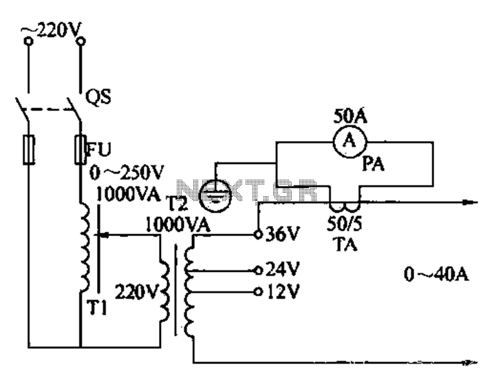
Electricians sometimes use overcurrent relays, thermal relays, and other devices to perform periodic overcurrent checks with a current generator. A secure running lights transformer, voltage regulator, and meter can be constructed using a small electric current generator. The homemade...
In the typical dynamo charging circuit, B+ and B- are the battery connections. D+ and D- go to the dynamo brushes, while DF is the field connection, with its other end returned to D+ inside the dynamo. Please note...
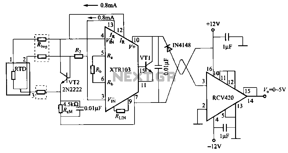
When the RTD temperature sensor is positioned far from the amplifier, the resistance of the sensor leads and their susceptibility to interference and other issues cannot be overlooked. The circuit shown in the figure addresses this problem. It utilizes...