
Laser Listening Device

The circuit under discussion utilizes various components to achieve its functionality. Key elements include resistors, capacitors, transistors, and diodes, each serving specific roles in the overall design.
Resistors R1 (100 MΩ), R2, R4, R10, and R15 (10 kΩ each), R3 and R8 (390 kΩ each), R5, R14, and R16 (1 kΩ each), R6/S1 (10 kΩ potentiometer and switch), R7 (2.2 kΩ), R12 (5.6 MΩ), R13 (39 kΩ), R17 (22 kΩ), and R9 and R11 (220 Ω each) are utilized to control current flow and set voltage levels throughout the circuit.
Capacitors play a crucial role in stabilizing the circuit and ensuring proper coupling between different points. Capacitor C1 (470 pF disc), C2 and C10 (100 µF 25V electrolytic), C3 and C9 (1000 pF disc), C4 (0.05 µF Mylar), C5 (10 µF 25V electrolytic), C6 (0.01 µF 25V disc), and C7, C8, C11, C12, C13, and C14 (2.2 µF 25V non-polarized) are employed for these purposes.
Transistors Q1 (L14G3 ultra-high sensitivity phototransistor) and Q2, Q3, Q4, and Q5 (PN2222 NPN transistors) are integrated into the circuit to amplify signals and control switching operations.
Diodes D1 and D2 (IN914) are included for protection against reverse polarity and to ensure proper signal flow.
The circuit also incorporates connectors, specifically J1 (RCA phono jack) and P1 (RCA phono plug), for interfacing with external devices. A battery clip (CL1) is utilized for power supply, and T1 (1 kΩ / 8 Ω mini audio transformer) is included to match impedance and facilitate audio signal transmission.
Overall, this circuit design integrates various electronic components to enhance the performance of the laser receiver, addressing challenges such as saturation and background noise while exploring the potential for increased operational range.Second, I have found that when the receiver was centered in the brightest spot (middle) of the reflected laser beam the circuit worked poorly compared to when the receiver was placed off-centered. This probably indicated that the circuit was saturated when the receiver was centered. And when it was off-centered, the circuit was able to analyze the weaker (less saturated) laser signal better. This must show that the lower energized beam was better able to become modulated when the beam was contacting the sound source. This can be useful in that this can mean that the laser can be sent at a longer distant to work even better.
And the thickness of the plane where the sound source is found can also affect the performance of the receivers capability to detect any changes in the signal. The thinner the plane, the easier it will vibrate and the better for the laser to be come modulated. Although it was said that the greater the distance the laser and the sound source the better the chance the laser will diverge larger giving a weaker signal (which prevents the over-saturation of the circuit) there will come limitations to this process.
So, using lenses to converge a larger area of the reflected beam to the receiver will help increase the range of the laser snooper even more. It was printed that the range may be as large as 300 feet versus the current 30 feet range. Although this isn`t really an electronic project, one way to think about as a future design is to implement Jake Janovetz`s Napoleon 56K DSP board to filter out background noise.
Background noise was very present from the receiver, and using the DSP board might have helped out in making the receiver work even better than it was designed for. This project has helped me relearn the theories learned from ECE342. Transistors were used to bias currents yielding different voltage levels. And capacitors were used to couple points of the circuit to stabilize. R1 1 100 Meg 1/2 Watt Resistor R2, 4, 10, 15 4 10 K 1/4 Watt Resistor R3, 8 2 390 K 1/4 Watt Resistor R5, 14, 16 3 1K 1/4 Watt Resistor R6/S1 1 10 K Pot and 12 V Switch R7 1 2.
2 K 1/4 Watt Resistor R12 1 5. 6 Meg 1/4 Watt Resistor R13 1 39 K 1/4 Watt Resistor R17 1 22 K 1/4 Watt Resistor R9, 11 2 220 Ohm 1/4 Watt Resistor C1 1 470 Pfd Disc Cap C2, 10 2 100 Mfd 25 V Elect Cap C3, 9 2 1000 Pfd Disc Cap C4 1. 05 Mfd Mylar Cap C5 1 10 Mfd 25 V Elect Cap C6 1. 01 Mfd 25 V Disc Cap C7, 8, 11, 12, 13, 14 6 2. 2 Mfd 25 V N. P. Cap C15, 16 2 1 Mfd 25 V Elect Cap Q1 1 L14G3 Ultra High Sen Phototransistor Q2, 3, 4, 5 4 PN222 NPN Transistor D1, 2 2 IN914 Diode J1 1 RCA Phono Jack P1 1 RCA Phono Plug CL1 1 9 V Battery Clip T1 1 1 K / 8 Ohm Mini Audo Transformer
🔗 External reference
Related Circuits
This document tells about one of my experiments with semiconductor laser modules. I bought one semiconductor laser for all kinds of experiments. This TIM202 module is a small (38x14x14 mm) semiconductor laser module, similar to those types used in...
This project was a final assignment for an optics class (EE 134) at Stanford University. It was an open-ended task aimed at creating a fully functioning laser microphone. The class focused on demonstrating optics and photonics in the laboratory...
A keyboard key functions by establishing an electrical contact between the surface of the keyboard and the underlying circuit when the keytop area is pressed. This mechanism was utilized by some home computers in the early 1980s and has...
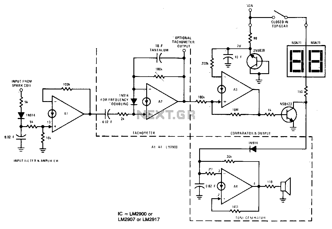
A1 amplifies and regulates the signal from the spark coil. A2 converts frequency to voltage so that its output is a voltage proportional to engine RPM. A3 compares the tachometer voltage with the reference voltage and turns on the...
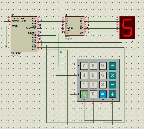
The IR photo transistor Q1 (Radio Shack 276-145A) or a similar component is connected to the set input (pin 6). It is essential to shield the photo transistor from direct light to ensure that the voltage at the set...

Controlling devices using switches is common. Over the past few decades, remote control switches such as infrared remote control switches, wireless remote control switches, and light-activated switches have gained popularity. However, these technologies have their limitations. Laser beams can...