
Laser Disc Player Modification
The modification process described involves several technical steps that require a solid understanding of electronic components and circuit design. The custom AC-3 board is essential for enabling Dolby Digital playback on older laserdisc players that do not have native support for this format. The careful selection of surface mount components is critical for maintaining signal integrity and minimizing noise, which is crucial for high-fidelity audio reproduction.
The installation requires precise drilling and soldering skills to ensure that all connections are secure and that no foreign material contaminates the internal components of the player. The use of coaxial cable for routing the RF signal is standard practice in audio electronics, as it helps to preserve the quality of the signal over distance. Furthermore, the AC coupling through a capacitor is a common method used to block DC components while allowing the AC audio signal to pass, which is essential for proper audio output without distortion.
Overall, the modification enhances the functionality of the Pioneer CLD-D702 laserdisc player, allowing it to utilize modern audio technology while preserving the value of existing laserdisc collections. The detailed steps outlined provide a clear pathway for enthusiasts and technicians who wish to undertake this modification, emphasizing the importance of caution and precision throughout the process.Many of us who invested in Prologic decoders are now looking at Dolby Digital. New formats like DSS, DVD-Video and High Definition Television incorporate this new technology; but what about the old laserdisc format After all, more than 600 laserdiscs feature Dolby Digital/AC-3 audio. For those people who do not currently have the AC-3 RF output on their laserdisc players, this site will
hopefully help you understand what is involved in modifying a player to support the Dolby Digital RF bitstream. The following shows a step-by step procedure on how to modify a Pioneer CLD-D702 laserdisc player to output the Dolby Digital (AC-3) RF signal needed to drive Dolby Digital demodulators/decoders.
My intention is to help those interested in modifying their own player; thereby avoiding the cost of upgrading to a new machine or paying a large sum of money to services that provide the Dolby Digital modification. This modification is to be done AT YOUR OWN RISK and there is no guarantee that the modification will work for you.
Failure to properly install this design correctly may result in damage to you and/or your laserdisc player. This web site takes no responsibility for any modification you may attempt. The custom board shown here holds the required AC-3 circuitry. Once installed, the card enables older, non-AC-3 laserdisc players the ability to output the much talked about AC-3 RF signal.
This version of the board uses metal film surface mount resistors as well as surface mount ceramic capacitors and transistors to minimize the level of noise in the signal. Players which have the AC-3 circuitry from the factory, typically use surface mount components as well.
The card was constructed using an iron-on type film which was generated on a laser printer from an inexpensive artwork program. Once the film was transfered, the board was put into etching solution to remove the unwanted copper. This is how the inside of the Pioneer CLD-D702 player looked prior to any modifications made to the unit.
The COXB Assembly board (unrelated to the AC-3 circuitry) located in the upper right corner of this picture, will be used to mount the new AC-3 circuit board using the predrilled hole provided by Pioneer. The new circuit card needs two voltage forms (+5VDC, -5VDC) and a ground. Power is tapped from these three lines as indicated in the photo. Red carries the +5VDC; Green carries the -5VDC and Black is ground. These power lines are routed to the newly installed AC-3 card. The AC-3 RF output is sent to the back panel through an RCA connector. Make sure when you drill the hole you don`t let any metal pieces fall into the unit. I used some tape and paper to cover the inside during drilling. Once the hole is drilled out, the RCA connector is installed with nylon washers to insulate the connector from the chassis.
Note: The outer portion of the connector will eventually be AC coupled to the chassis through a 0. 1uF capacitor. The wire shown on the back of the Audio Assembly card is the mute signal connected to pin 10 of CN201. The signal is difficult to tap from on the component side. Therefore, I chose to make the connection on the solder side. Connector CN201 interfaces with J10 on the Main Assembly board. This active high MUTE signal is needed to properly set the DC level of the AC-3 RF signal during the mute mode.
The AFM RF signal that is used to carry both the left and right analog audio is tapped from the emitter of Q352 (2SC1740S). The AFM RF signal is located on the pin of Q352 closest to L353 as shown in the picture. The ground is connected to the jumper wire located next to R357 as shown. This coaxial signal is routed to the custom AC-3 card using RG-179 coaxial cable. Note: The current AC-3 RF outputs on production LD players contain both the left a 🔗 External reference
Related Circuits
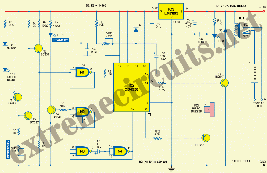
This automatic door opener can be constructed using readily available components. The electromagnetic relay at the output of this device can be utilized to control the door mechanism. The automatic door opener circuit is designed to facilitate the opening of...
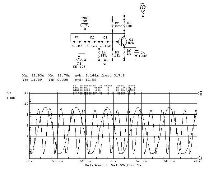
This circuit design for a laser diode driver can be implemented using a voltage-controlled current source. This simple linear laser diode driver provides a cleaner drive current compared to switched (PWM) drivers. The circuit is based on the OPA350...
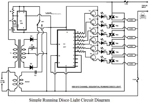
This article explains how to design a minimal Running Disco Light Circuit Diagram using the IC 4017. The IC 4017 is a 16-pin dual in-line package integrated circuit that includes a 10-stage decade counter. The design operates on 230V...
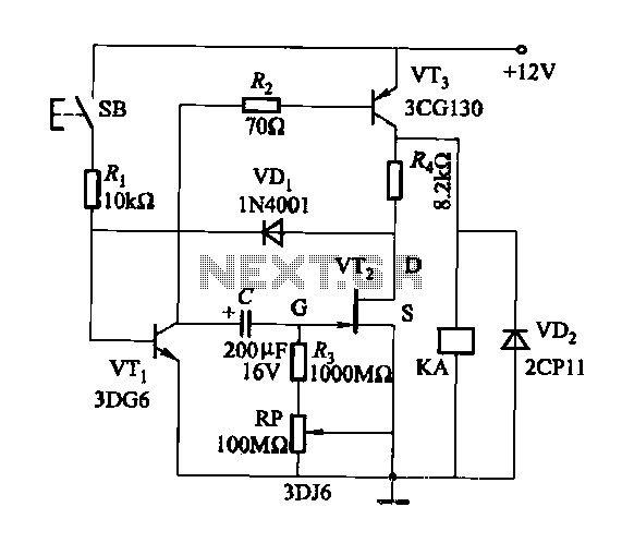
Discharge time relay circuit. The timer utilizes a field effect transistor, providing high timing accuracy and extended timing capabilities. With R3 set to 1,000,000 ohms and C at 200 microfarads, a delay time of 8 hours can be achieved....
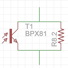
A simple method can be tried that may not be as accurate as professional scientific tools but appears to be more reliable than some manufacturers' claims. A resistor should be wired in parallel with the photodiode to mitigate saturation...

This circuit features high stability and precision, providing a direct current source that can be preset for various electronic devices. The numerical control direct current source designed here effectively reduces output errors caused by component wear, temperature drift, and...
Warning: include(partials/cookie-banner.php): Failed to open stream: Permission denied in /var/www/html/nextgr/view-circuit.php on line 713
Warning: include(): Failed opening 'partials/cookie-banner.php' for inclusion (include_path='.:/usr/share/php') in /var/www/html/nextgr/view-circuit.php on line 713