
laser door alarm circuit

The laser door alarm circuit is designed for simplicity and effectiveness in security applications. The laser transmitter, a standard laser pointer, provides a focused beam that can cover a distance sufficient to monitor doorways effectively. The positioning of the laser pointer is crucial; it must be aligned with the phototransistor to ensure reliable operation.
The receiver section's choice of the L14F1 NPN Darlington phototransistor is significant due to its high sensitivity and fast response time, allowing for quick detection of beam interruptions. The voltage comparator IC1 plays a vital role in processing the signals from the phototransistor. By maintaining the inverting input at half the supply voltage through the resistive divider, the circuit is designed to minimize false alarms while ensuring a quick response to legitimate interruptions.
The output stage of the circuit utilizes a transistor (T2) to drive the buzzer and LED. The inclusion of capacitors C1 and C2 is a thoughtful design choice, providing a delay that allows the alarm to sound for a few seconds even after the interruption has ceased. This feature enhances the circuit's effectiveness, ensuring that the alarm is noticeable and serves as a deterrent.
Overall, this laser door alarm circuit exemplifies a straightforward yet efficient approach to security, leveraging basic electronic components to create an effective monitoring system. Proper assembly and calibration of the components will ensure the reliability and functionality of the alarm system in real-world applications.This is a circuit for laser door alarm is based on the interruption of Laser beam. A low cost Laser pointer is used as the source of light beam. When somebody breaks the laser path, the alarm will be generated for few seconds. This is the figure of the circuit; The laser door alarm circuit has two sections. The laser transmitter is a laser pointer readily available. It should be powered with 3 volt DC supply and fixed on one side of the door frame. The receiver has a Phototransistor at the front end. L14F1 NPN Darlington phototransistor is used as the laser sensor. IC1 is used as a voltage comparator with its inverting input tied to a potential divider R2-R3. So that the inverting input is kept at half supply voltage. As a result, output of comparator remains low. LED and Buzzer remain off in this state. When a person crosses the door, laser beam breaks and T1 cease to conduct. Collector voltage of T1 rises and voltage at pin 3 of comparator increases and its output becomes high. This activates LED and buzzer. Capacitor C1 keeps the base of T2 high for few seconds even after the output of IC1 becomes low again.
C2 gives current to the buzzer for few seconds even after T2 turns off. 🔗 External reference
Related Circuits
This circuit is designed to drive a total of 42 LEDs, assuming a forward voltage of approximately 2.2V per LED and a forward current of around 21mA for adequate brightness. If the specifications of the LEDs differ significantly, modifications...
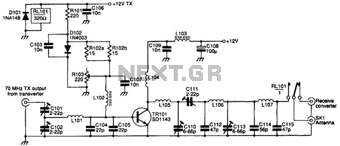
The SD1143 transistor offers a gain of approximately 14 dB in this circuit. Its design takes advantage of the fact that a 175-MHz device exhibits significantly higher gain when operated at lower frequencies. The amplifier was initially intended for...
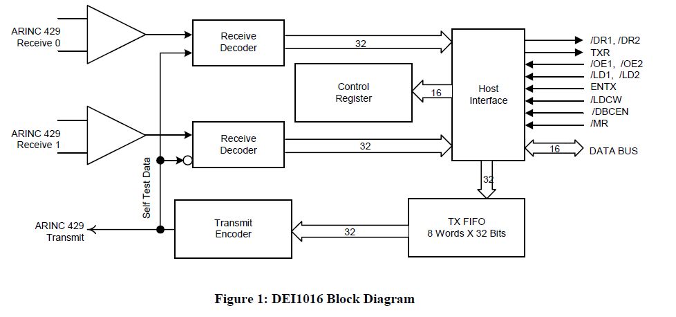
This document outlines the process of interfacing an Arduino with an ARINC 429 transceiver, illustrating the general methodology for connecting an Arduino to electronic circuits that can be applied to individual designs. The ARINC 429 bus is the predominant...
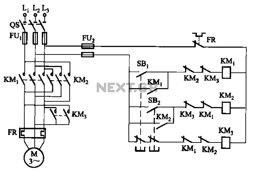
The circuit depicted in Figure 3-154 illustrates the KM3 braking contactors. During shutdown, the system can disconnect the operating system. At this point, KM3 activates, causing its normally open contact to close, thereby shorting the three-phase stator windings to...
The proximity detector detects the movement of PC board pieces as the wheel rotates, generating an output signal with a clear transition between high and low voltage levels, making it suitable for triggering counting or processing circuits. Following this...
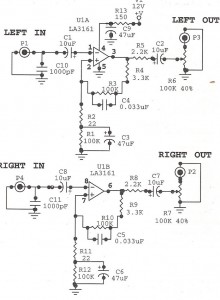
Preamplifiers are utilized to amplify low-level signals, such as those from microphones and tape heads, before they are sent to power amplifiers. Power amplifiers typically exhibit lower sensitivity. The frequency response can also be adjusted and optimized at the...
Warning: include(partials/cookie-banner.php): Failed to open stream: Permission denied in /var/www/html/nextgr/view-circuit.php on line 713
Warning: include(): Failed opening 'partials/cookie-banner.php' for inclusion (include_path='.:/usr/share/php') in /var/www/html/nextgr/view-circuit.php on line 713