
Laser Microphone

The laser microphone system operates on the principles of optics and photonics, utilizing a laser beam to detect sound vibrations from surfaces. The optical design incorporates a laser beam splitter, mirrors, and a photodiode for signal detection. The beam splitter divides the laser light into two paths: one directed towards the vibrating surface and the other serving as a reference. The laser's modulation by the audio signal allows for the detection of vibrations through the Doppler effect, where the frequency of the returning beam is altered based on the movement of the surface.
The photodiode converts the optical signal back into an electrical signal, which is then amplified and filtered to enhance quality. The system's design allows for effective sound detection at a range of distances, making it suitable for applications in surveillance and research. Furthermore, the ability to analyze vibrations beyond audio frequencies expands the potential uses of this technology in various fields, including structural health monitoring and material testing.
The performance metrics of the laser microphone, such as the signal-to-noise ratio and percentage of laser power recovered, indicate its effectiveness in real-world applications. The described setup demonstrates a significant advancement in non-invasive audio capture methods, highlighting the importance of precise optical alignment and signal processing in achieving high-fidelity results.This was a final project for an optics class EE 134 at Stanford. It was an open-ended project to make a fully functioning laser microphone the class was geared to demonstrate optics and photonics in the lab, not necessarily electrical schematics. There are real commercial devices that use lasers to sense sound acoustics from glass surfaces. The hardest aspects of this sort of project were getting all the optics to line up and work properly. The final write-up is included here. A laser microphone was constructed and demonstrated. The laser was able to successfully detect audio vibrations and recover the signal in a useful form for processing. Electrical circuits provided amplification and filtering which improved signal quality. After recovery, the audio signal was output to a speaker. The system had a signal-to-noise ratio of 3. 7 dB and recovered about 25% of the laser power at variable distances from 15 to 80 cm. Laser microphones are capable of detecting sound at distances and through mediums that traditional equipment cannot.
Law enforcement or other surveillance experts employ many techniques and equipment in order to gather information. A traditional G ‚¬ bugG ‚¬ is an electronic device that is physically placed near or inside enclosures which transmits audio information via radio or other short-ranged frequencies.
With the use of a laser, entry into a building in order to plant a bug is not necessary. Instead, only a direct line of sight to a window or other vibrating surface will suffice in order to sample and receive audio information. Techniques demonstrated in this paper could also be employed to perform high sensitivity studies on any vibrating surface and need not be limited to audio frequencies.
Laser vibrometry is a technique to measure the velocity of vibrating surfaces by detecting doppler shift in frequency. This approach detects phase shift of an interferometer instead of direct frequency modulation as used in this project.
The optical stage directs laser light through a beam splitter. The forward path strikes a mirror which is mounted on a speaker head. The laser is directly modulated by the speaker by an audio signal. As the beam returns, it passes back through the beam splitter and is focused using an objective lens onto a photodiode. The second path which splits from the beam splitter is reflected back by a reference mirror and then recombined at the beam splitter with the first returning beam.
In a true interferometric system, the second branch of the beam splitter is used as reference to detect the phase difference caused by the changing path length of the first branch. In this way, very small vibrations can be detected by examining the signal at the photodiode. Figure-1 illustrates the basic schematics of the optical design implemented. The laser used in this project operated at 1550nm. A laser wavelength of any size would be sufficient fided about 1 to 5mV of input and modulated the speaker with similar characteristics of a real-world system.
The second type of input came from a function generator. The minimum voltage that this lab equipment could provide was 50mVpp. Instead of providing a low-voltage signal, the function generator was used to determine fidelity of the system at variable frequencies from 20 Hz to 1. 5 kHz. It was found that about 200 Hz the input of the cember 2006. 🔗 External reference
Related Circuits
Read the generic sound level from an electret microphone. Several schematics utilize NPN transistors that yield an inverted output (~5V when quiet, ~0V when loud, with linear operation in between). However, a non-inverted output is desired, where a super...
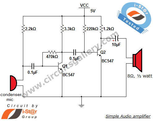
This circuit diagram is a simple and effective design for amplifying weak signals from a capacitive condenser microphone. It is suitable for sound sensing applications and various automatic robotic sensors. While a more complex audio amplifier circuit using the...
This chapter provides detailed schematics of various power supplies suitable for use with common Ar/Kr ion tubes available to hobbyists in the surplus market. Included are examples of commercial designs (Omnichrome 150R and 532 head, Lexel 88 and head)...
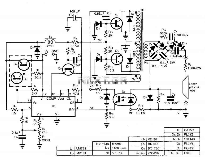
The circuit employs a free-running push-pull DC to DC high voltage converter to generate the required voltage for the laser plasma tube supply. The supply voltage (Vc) of this converter is regulated by a switch-mode power supply to maintain...
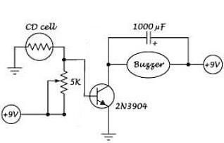
This is a simple and inexpensive instructable for creating a laser burglar alarm. The necessary components include: 1. LDR (Light Dependent Resistor) or photocell 2. Printed circuit board. The laser burglar alarm circuit utilizes an LDR or photocell as a...
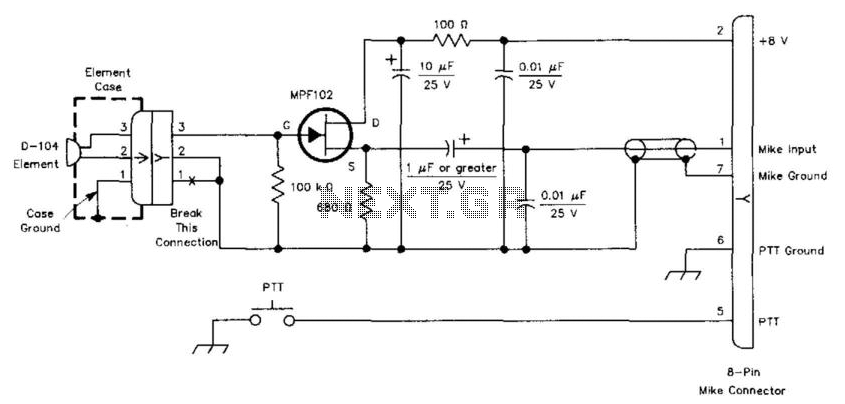
This circuit is designed to interface a high-impedance microphone with a radio transceiver that requires a low-impedance microphone. The power supply can be provided either by a battery or sourced from the transceiver itself. This circuit typically employs a preamplifier...