
LASER BURGLAR ALARM

The laser burglar alarm circuit utilizes an LDR or photocell as a key sensing element to detect interruptions in a laser beam. When the laser beam is broken, the change in resistance of the LDR triggers an alert mechanism, indicating a potential intrusion.
The circuit can be designed with the following components:
1. **Laser Diode**: This serves as the light source, emitting a coherent beam that can be directed toward the LDR.
2. **LDR (Light Dependent Resistor)**: Positioned in the path of the laser beam, the LDR’s resistance decreases when exposed to light from the laser diode. When the beam is interrupted, the resistance increases, which can be detected by the circuit.
3. **Resistor**: Used in series with the LDR to form a voltage divider that allows for the detection of changes in light intensity.
4. **Transistor**: Acts as a switch or amplifier to control an alerting device, such as a buzzer or LED, when the LDR detects a change in light levels.
5. **Buzzer or LED**: This output component provides an audible or visual alert when the laser beam is interrupted.
The circuit can be assembled on a printed circuit board (PCB) for durability and ease of use. The laser diode should be positioned to ensure that the beam is aimed directly at the LDR, with appropriate alignment to achieve maximum sensitivity.
Power supply considerations should also be made, with suitable battery or DC power options selected to ensure reliable operation. The overall design can be compact, making it easy to install in various locations for security purposes.
This simple laser burglar alarm can serve as an effective deterrent against unauthorized access, providing a cost-effective solution for home and property security.Hi guys..!!this is my 1st easy cheap n simple instructabel u need following components for laser burglar alarm-1. LDR or photocell 2.printed circui.. 🔗 External reference
Related Circuits
This project was undertaken in June 1996 as a final year electronics project. The circuit was constructed using individual components, including logic gate integrated circuits (ICs) and a keyboard decoder IC. Since then, electronics has advanced, and if created...
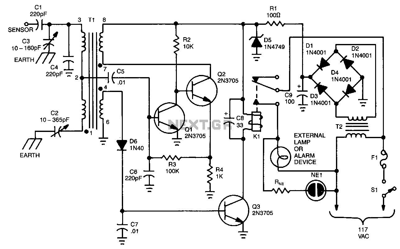
The unit is built around a balanced-bridge circuit that utilizes both capacitance and inductance. The bridge comprises capacitors C2 and C3, along with the center-tapped winding of transformer Tl. One end of the bridge is connected to ground through...
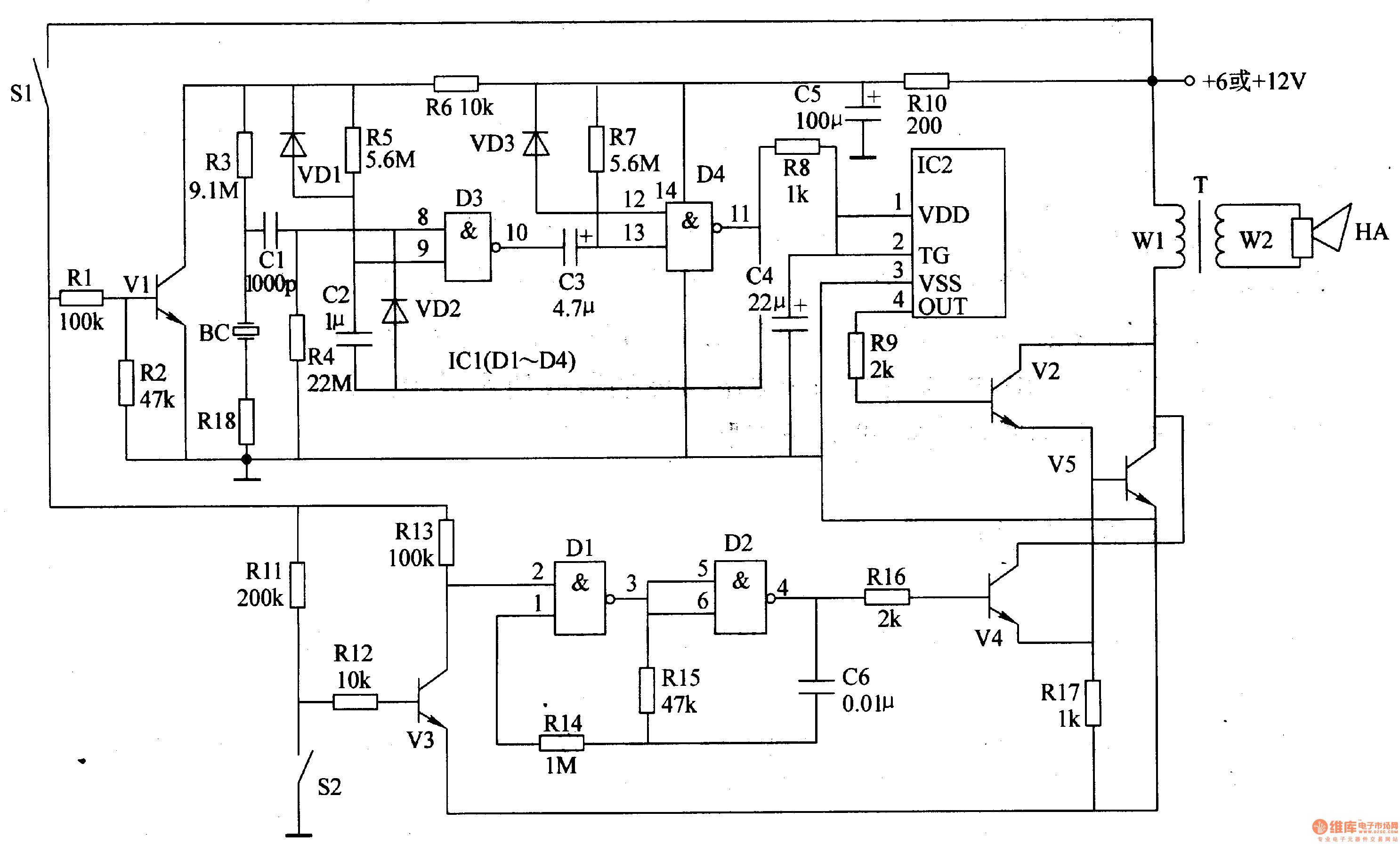
The motorcycle anti-theft alarm circuit consists of several components, including the anti-theft detection circuit, the control circuit, the sound generator, the audio oscillator, and the power amplifier output circuit, as illustrated in figure 7-91. The anti-theft detection circuit is...
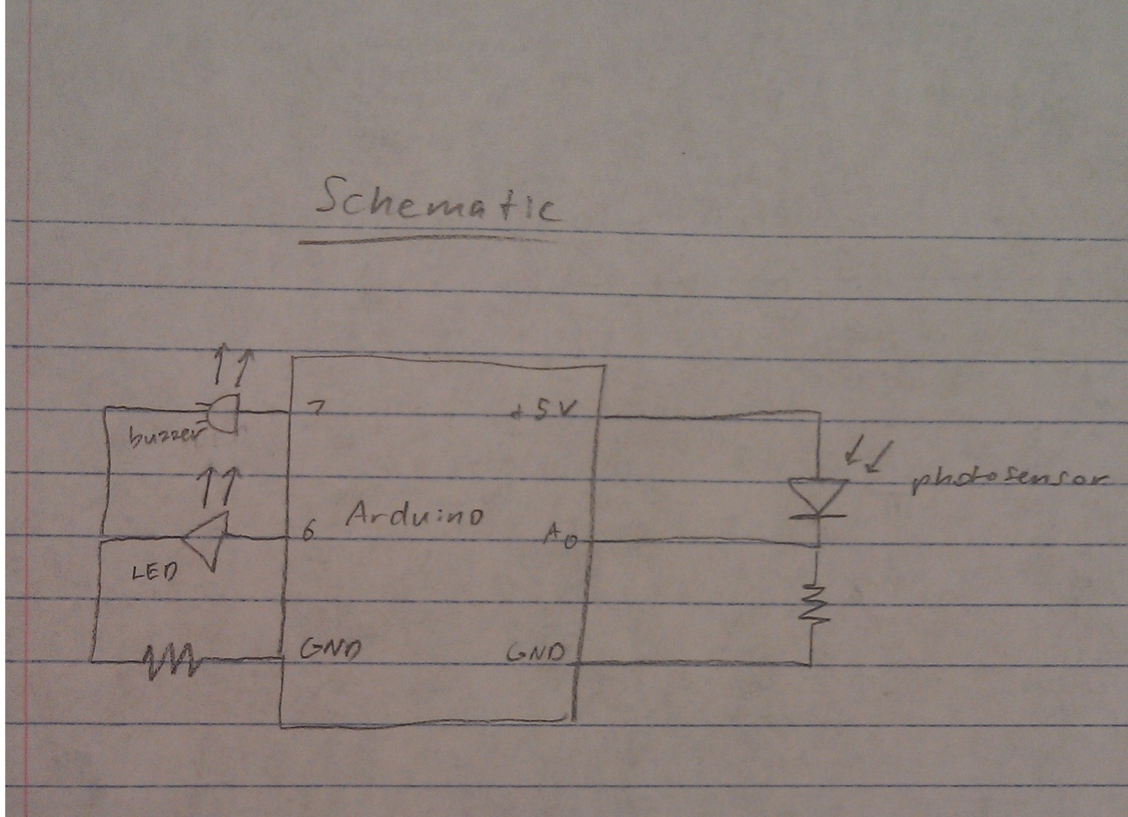
A nightlight combined with a wake-up alarm has been developed. This nightlight incorporates six LEDs that activate when a photosensor detects low ambient light levels. Additionally, a buzzer plays a cheerful tune when ambient light levels increase again. The...
The frequency is controlled by pin 5 of the integrated circuit (IC). When the power supply is activated, the capacitor charges gradually, which alters the voltage at pin 5 of the IC, causing the frequency to increase incrementally. Once...
The speed of light has been measured using various ingenious methods. This note describes a conceptually simple and relatively easy-to-implement technique known as the time-of-flight optical pulse delay method. It utilizes a short (nanosecond) optical pulse and an oscilloscope...