
Laser Power Supply
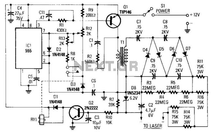
The circuit described utilizes a 555 timer (IC1) configured in astable mode to generate a square wave signal at a frequency of approximately 16 kHz. This frequency is suitable for driving a power transistor (Q1), specifically a TIP146, which acts as a switch to control the primary side of transformer T1. The transformer steps up the voltage, allowing for high voltage generation across its secondary winding. The output voltage can vary significantly, ranging from 800 to 2,000 V, which is then further doubled to achieve a high-voltage output of 3 to 5 kV, essential for applications such as laser excitation.
The circuit includes a feedback mechanism that monitors the load on the power supply. As the load increases, transistor Q2 is triggered, which activates relay RY1. The engagement of the relay modifies the duty cycle of the 555 timer, allowing for dynamic adjustment of the output voltage to meet the demands of the load.
For calibration, resistors R12 and R13 are critical components. They are initially set to their mid-range values, allowing for fine-tuning of the circuit's response. Adjusting R12 influences the triggering of the laser tube; if the laser does not ignite, further adjustments to R12 are necessary. Should the relay exhibit chattering behavior during operation, indicating instability, additional tuning of R12 is required until stable operation is achieved. In cases where the laser tube does not ignite despite maxing out R12, it is advised to adjust R13 to ensure proper functioning of the circuit.
This design exemplifies a robust method for generating high voltage for laser applications, with built-in adjustments for load variations, ensuring reliable performance and operational flexibility. ICl is a 555 timer running at about 16 kHz. This IC drives Ql, a TIP146, which produces a 12-V square wave across Tl pri mary. This produces between 800 and 2,000 V across the secondary, which is doubled to 3 to 5 kV. When the load (laser) on the power supply increases, current Q2 is turned on, which energizes RY1. This changes the duty cycle of the 555 timer, lb adjust this supply, set R12 and R13 at the center. Adjust R12 until the laser tube triggers, and make sure that the relay pulls in. If the relay chatters, adjust R12. If the full-clockwise adjustment of R12 fails to ignite the tube, adjust R13. 🔗 External reference
Related Circuits
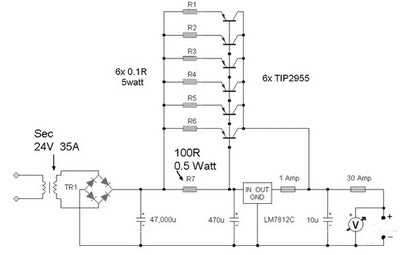
A 12 Volt 35 Amp power supply can be constructed using the LM7812 voltage regulator to provide a stable 12 Volt DC output. The power supply employs TIP2955 transistors as the main power regulators, with a configuration that utilizes...
This circuit can be adapted for other regulated and unregulated voltages by using different regulators and batteries. For a 15 Volt regulated supply use two 12 Volt batteries in series and a 7815 regulator. There is a lot of...
Vacuum tube electronic circuits operate from relatively high DC voltages (150 to 600 volts). The Electric Utility supplies 120 volts AC. Transformers can step up the 120 volts AC line voltage to the necessary range, but it remains AC....
This AC to DC power supply can output 5A in continuous operation and 12A peak current. This type of DC power supply utilizes a PCB, allowing for the use of two case types. The described AC to DC power supply...
This circuit is intended to indicate the power output level of any audio amplifier. It is simple, portable, and displays three power levels that can be set to any desired value. IC1A is the input buffer, feeding 3 voltage...

Voltage is transformed by the transformer turns ratio N2/N1. For instance, if a 20VAC secondary voltage is required with a 120VAC input, a 6:1 ratio would be needed. When full load current is drawn from the secondary winding, the...