
Power Conversion Principles

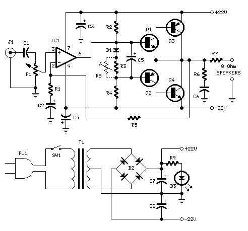
The described circuit involves a transformer that steps down the voltage from a higher AC input level to a desired lower AC output level, based on the turns ratio. In this specific example, a 6:1 turns ratio transforms 120VAC to 20VAC on the secondary side. The voltage regulation aspect is critical, as it indicates how much the output voltage can drop under full load conditions, which can vary significantly from 5% to 25%.
To enhance safety, a thermal fuse is integrated into the primary circuit, providing protection against potential short circuits or overloads on the output side. The circuit utilizes a capacitor, referred to as C1, which charges to approximately 1.414 times the RMS voltage of the secondary output, minus the voltage drop across the diode rectifiers. This capacitor plays a vital role in smoothing the rectified output, although loading conditions can lead to a drop in output voltage, typically between 20% and 30%, which is a key consideration for voltage regulation.
The design employs a center-tapped transformer configuration with two diodes; however, a more common configuration is the non-center-tapped transformer with four diodes, which can provide better efficiency in certain applications. The unregulated DC output from C1 is then fed into a linear voltage regulator that ensures a stable output voltage, which is crucial for sensitive electronic devices.
Capacitor C2 is included to stabilize the output of the regulator, preventing oscillations and enhancing transient response. The regulator operates effectively until the input voltage at C1 falls below a certain threshold, referred to as the low-line point, which is determined by the minimum voltage drop required for the regulator to function properly.
High-frequency switching techniques are employed within the regulator to optimize the size of the transformer and improve overall circuit efficiency. Various converter topologies, including forward, boost, flyback, and resonant configurations, can be utilized depending on the specific application requirements. In this case, a flyback converter is referenced, which uses PWM to control the output voltage by varying the duty cycle of the switching element.
For battery charging applications, the C/10 charging method is highlighted, indicating that the charging current should be set to one-tenth of the battery's Amp-Hour rating. This method typically requires 12 to 14 hours to fully charge a depleted battery. The circuit also incorporates a current limiting feature, which can be either resistive or electronic, to prevent excessive current flow during charging. An LED indicator is included to visually signal that charging is in progress.
To prolong the lifespan of lead-acid batteries, voltage-limited charging techniques are essential. At room temperature, a voltage of 2.3V per cell is necessary to maintain full charge. Maintaining a voltage tolerance of +/-1% is critical, achieved through voltage trimming techniques. With proper implementation, recharge times of 3 to 5 hours can be realized for standard lead-acid cells, thus enhancing the efficiency of the charging process.Voltage is transformed by the transformer turns ratio N2/N1. For instance if 20VAC secondary voltage is required with 120VAC input, a 6:1 ratio would be needed. When full load current is drawn from the secondary winding, the voltage may drop from 5 to 25%, this effect is known as voltage regulation. Addition of a thermal fuse to the primary circuit insures safe operation in the event of an output short circuit or overload. Capacitor C1 will charge up to 1. 414 times the RMS secondary voltage minus the diode drop. Applying a loading current will cause the output voltage to drop by about 20 to 30%, the percentage drop is referred to as the voltage regulation. The circuit shown uses a center-tapped winding and 2 diodes, a non- center-tapped winding with 4 diodes is probably the most common configuration.
Unregulated DC power supplied from C1 powers the linear regulator. The regulator will precisely control the output voltage for critical circuit applications. Capacitor C2 is used to prevent oscillations in the regulator, it also improves regulator transient response characteristics. When the voltage at C1 minus the minimum regulator drop falls below the output voltage rating, the regulator is at the low-line point.
This type of regulator utilizes hi frequency switching techniques to minimize transformer size and maximize efficiency. Various converter topologies are the forward, boost, flyback and resonant. The flyback converter shown at left uses PWM (Pulse Width Modulation) circuitry to regulate the output.
By modulating the switch at a fixed frequency with a given duty cycle the output voltage can be expressed as: The most common charging technique is the C/10 charger. C is the Amp/HR capacity of the battery. This type of charger requires approximately 12 to 14 hours to replenish a fully depleted battery. The current limiter can either be a resistive element or an electronic circuit. An indicating LED is useful for providing visual means to show charging is taking place. Voltage limited charging techniques are essential to extend battery life. At room temperatures lead acid cells require 2. 3V per cell to stay at 100% charge. Voltage tolerance of the charging circuit should be kept to +/-1% by the use of voltage trimming. Recharge times of 3 to 5 hours can be realized with standard lead acid cells. 🔗 External reference
Related Circuits
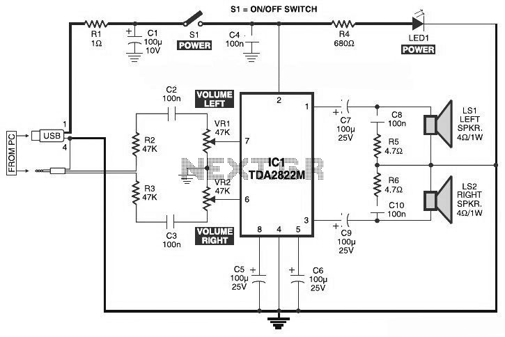
This is the circuit diagram of a USB-powered computer speaker, commonly known as multimedia speakers for PCs. The circuit features a single-chip design, operates on a low-voltage power supply, and is compatible with USB power from a computer. The USB-powered...
This is a circuit schematic diagram for a power amplifier utilizing the IC TLE2141C. The TLE2141C is a low-noise, high-voltage, high-slew-rate operational amplifier. It offers a frequency response from 30 Hz to 20 kHz with a variation of 1...
Nearly all modern computers are equipped with logic blocks that facilitate the implementation of a USB port. A USB port can deliver over 100 mA of continuous current at 5V to peripherals connected to the bus. Therefore, it serves...
Vacuum tube electronic circuits operate from relatively high DC voltages (150 to 600 volts). The Electric Utility supplies 120 volts AC. Transformers can step up the 120 volts AC line voltage to the necessary range, but it remains AC....

This method can be illustrated using an uncommon semiconductor power flip-flop. A flip-flop is a toggling circuit with two stable states (bistable multivibrator) that retains its output state without an input pulse. Triacs can be used to implement flip-flops...
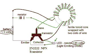
This circuit is known as the Joule Thief. For those unfamiliar with it, an image of the circuit is provided. The Joule Thief is a minimalist circuit designed to extract usable voltage from a low-voltage power source, such as a...