
LED Audio Power Indicator
This audio power level indicator circuit is designed to provide a visual representation of the output power levels from an audio amplifier. The circuit utilizes a standard operational amplifier (IC1A) configured as an input buffer to ensure that the input impedance is high enough to avoid loading the amplifier output. The buffered signal is then fed into three voltage comparators, which compare the buffered audio signal to predetermined reference voltage levels set by a voltage divider network.
The output of each comparator is connected to an LED driver, which illuminates corresponding LEDs to indicate the power output level. The reference voltages can be adjusted to accommodate different amplifier outputs, allowing for flexibility in monitoring various audio devices. The smoothing action provided by resistor R5 and capacitor C4 ensures that the signal is stable and free from noise, enhancing the accuracy of the readings.
For optimal setup and calibration, an oscilloscope or an audio millivoltmeter is recommended to measure the output of the amplifier accurately. This allows for precise adjustment of the reference levels to ensure that the LED indicators accurately reflect the power levels being output by the amplifier. Additionally, a 1KHz sine wave generator with variable output is necessary for testing purposes, enabling the user to simulate various audio signals and observe the corresponding LED responses.
The circuit can be easily connected to the amplifier's output using a twisted pair cable, which helps to minimize interference and maintain signal integrity. The use of insulated crocodile clips for connection ensures safety and ease of use during setup. Overall, this circuit is a practical solution for audio engineers and enthusiasts seeking to monitor amplifier performance in real-time.This circuit is intended to indicate the power output level of any audio amplifier. It is simple, portable, and displays three power levels that can be set to any desired value. IC1A is the input buffer, feeding 3 voltage comparators and LEDs drivers by means of a variable dc voltage obtained by R5 and C4 smoothing action. The simplest way to connect this circuit to the amplifier output is to use a twisted pair cable terminated with two insulated crocodile clips.
Setup is best accomplished with an oscilloscope or an audio millivoltmeter like the one described in these pages. Precision Audio Millivoltmeter A 1KHz sine wave generator with variable output is also required (see a suitable circuit in this website als
🔗 External reference
Related Circuits
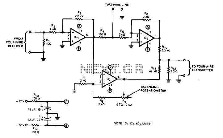
This audio converter circuit maintains 40 dB of isolation between the two halves of entry and exit of a four-line system while allowing a line connection between the two systems. A balancing potentiometer, R, adjusts the gain of the...
The circuit consists of two stages. The first stage is a switch or cut-off device. It detects a voltage above 0.7V from the solar panel, and the resistance between its collector-emitter terminals reduces to a very small value. The...
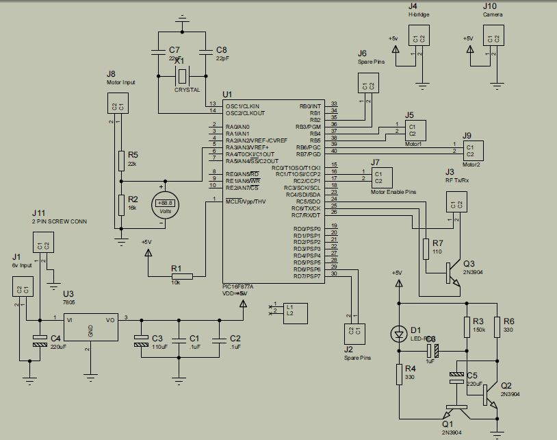
The project is developed by Team Stark, with Gilbert as the leader and team members Martin and Janssen. The tasks have been divided into three parts. The first part includes camera control, login database, installer, and network setup, which...
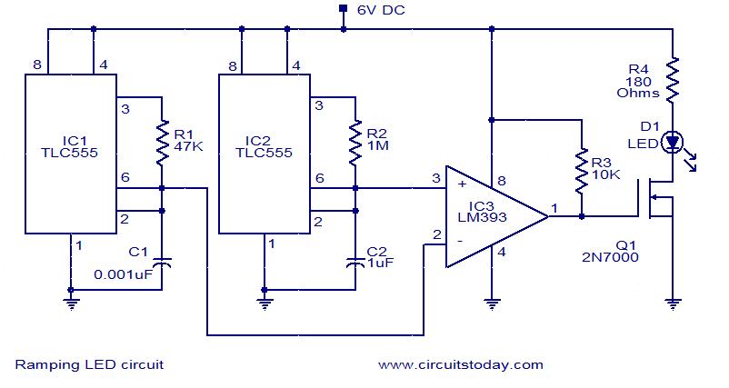
In this circuit, the intensity of the LED varies in a ramping fashion. The circuit comprises three integrated circuits: two 555 timer ICs and one LM393 operational amplifier. IC1 and IC2 are configured as oscillators to generate frequencies of...

Creating a variable space in a small room can be enjoyable; however, designing an actuator to move a wall or room partition poses challenges. This can be achieved using an analog audio line delay. To implement a system that allows...
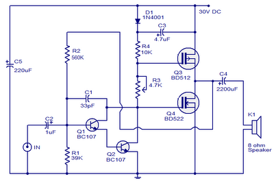
This is a 10W MOSFET audio amplifier circuit that operates from a single power source. Single rail configurations are seldom used in Class B power amplifiers; however, they are suitable for low-power applications like this one. This circuit design...