
Latch Switch
This circuit utilizes a non-locking push switch (S1) to control the activation of a load, which can be represented by various components such as a resistor (R5) and a diode (D1), or potentially a lamp or relay. The circuit is designed such that the load remains activated until the power supply is interrupted. An optional switch (S2) can be included to break the power supply to the circuit, allowing for a reset mechanism. If S2 is excluded, the only method to reset the circuit would involve disconnecting the power source, such as unplugging a battery or disconnecting from an electrical outlet.
Upon initial power application, or when S2 is toggled, the capacitor (C1) begins to charge through the base-emitter junction of the transistor (Q1). This charging process generates a brief positive pulse at the base of Q1, which causes Q1 to enter saturation. In the saturated state, the collector-emitter voltage of Q1 approaches zero volts, effectively allowing current to flow through the load. With Q1 in this state, the second transistor (Q2) remains off, preventing any unwanted activation of additional components in the circuit.
The design of this circuit is particularly useful in applications where a momentary switch is desired to control a load that remains on until power is removed. The inclusion of C1 allows for a smooth transition during the activation phase, ensuring that the load is turned on reliably. The optional switch S2 provides flexibility for the user, enabling a straightforward method to reset the circuit without needing to physically disconnect the power supply. Overall, this circuit offers a simple yet effective solution for controlling various loads in electronic applications.In this circuit a non-locking push switch is used to activate a load. The load remains switched on until power is removed from the circuit. The load is represented by R5 and D1, but could be a lamp, a relay or another circuit. S2 breaks power to the circuit but could be omitted altogether. If S2 is left out, then reset would be by disconnecting the power; this would mean unplugging the battery if battery powered or disconnecting from the electrical outlet. When first plugged in (or S2 is operated) C1 charges via the base emitter junction of Q1 and hence a brief positive pulse is applied. Q1 will switch on and be saturated, its collector emitter voltage being close to zero volts. Q2 is therefore off, and the 🔗 External reference
Related Circuits
The whistle switch allows you to turn on, or off, an appliance by whistling at it. I originally built the whistle switch in 1974. Do not attempt to duplicate it from the schematic below, but instead, understand the functions...
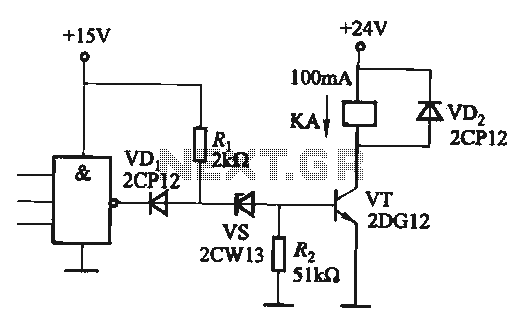
If the CMOS circuit load (actuator) is a relay device, the circuit must have a large load capacity. Non-gate drive switching amplifiers are connected to a separate element shown in the interface circuit. In the context of a CMOS circuit...
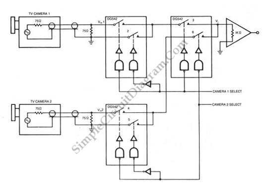
A video switch is necessary to multiplex several video sources, allowing multiple cameras to be displayed sequentially on a single monitor. This multiplexing process... A video switch serves as a critical component in video signal management, particularly in applications where...
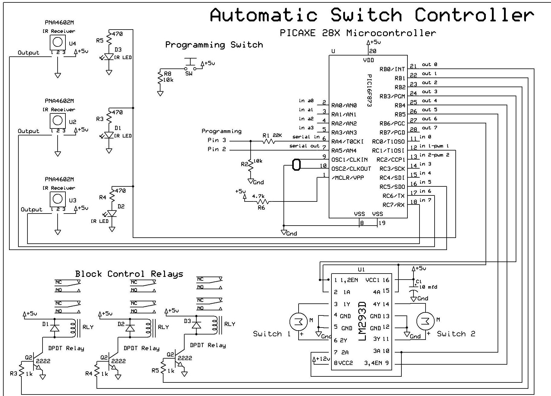
The objective of this controller project is to achieve automatic block and switch control for five separate engines operating on two independent loops of track. Each loop has both public and hidden sections. The inner loop accommodates three trains,...
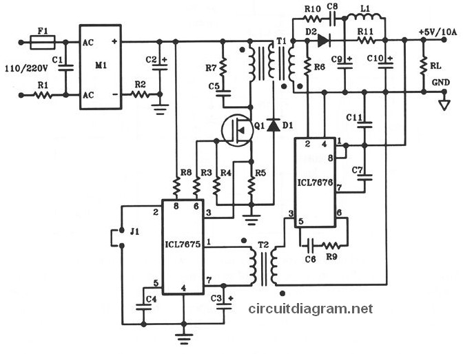
The following diagram illustrates the design of a 50W offline switching power supply circuit. This circuit is powered by a MOSFET, specifically the BUZ80A/IXTP4N8 for 220V AC input and the GE IRF823 for 110V AC input voltage. The output...
A highly versatile switch that can be controlled from any channel on a typical Futaba or JR radio setup. This switch was designed to trigger the shutter on digital cameras without the need for a servo attached to the...