
Schiepatti Switch

A simple demonstration of controlling an external object using an external power source is provided. In one configuration, the Schieppati Switch is powered by the receiver battery and awaits commands from the transmitter via the receiver. When an ON command is transmitted, it is processed by the receiver and executed by the Schieppati Switch. The switch can manage loads up to 36 volts DC and 0.8 amps in its basic configuration, with the potential for higher loads as outlined in further details. For controlling inductive loads, such as a coil-operated switch, precautions must be taken to prevent back EMF, which can damage the switch. A diode should be installed in parallel with the inductive load, with the cathode connected to the positive power supply and the anode connected to the ground side of the coil. This configuration allows the recirculation of excess reverse current generated when the circuit is opened.
To enhance safety, the switch can be optically isolated using an optocoupler chip, such as the TIL 111 photo transistor. In this setup, the Schieppati Switch activates the photo transistor, allowing an isolated circuit on the other side of the chip to operate, eliminating any electrical connection between the switch and the external load. The configuration can be adapted to drive multiple glow plugs by connecting two devices in parallel, increasing the current draw. In scenarios where a model aircraft crashes in hard-to-reach areas, a simple noise-generating circuit can be constructed that operates off the receiver battery and can be activated by the Schieppati Switch. This can be achieved by using a "Y" harness connected to any unused channel, linking the noise generator to one branch and the Schieppati Switch to the other, ensuring that the power supply is drawn from the receiver.A very useful switch that can be controlled from any channel on the typical Futaba or JR radio set up. The switch was designed to trigger the shutter on digital cameras without the encumbrance of a servo glued onto the camera.
However, apart from aerial photography, one of the more interestingfeatures is that it can be used to trigger external loads that draw power either from the receiver battery or another external power source. Of further interest, the switch can be programmed to trigger at a preset interval of time, such as every ten seconds. Equally, the really interesting function is that the output signal can be set up to trigger at a preset interval of time and/or on command from the transmitter.
Finally, the output signal can be programmed to be either a short pulse or a continuous ON command. That is flexibility! The power consumption of the switch is 0. 8mA when the Light Emitting Diode (LED) is OFF and 6. 5mA when the LED is ON, so there is no risk of discharging the battery with the switch. Michele`s switch is about as small and as light as you can possibly imagine. In the image, the three wire lead (black, red and white) goes to any spare channel on the receiver. The switch draws power from the receiver battery and gets the command signal on the white wire. Shown below is a simple demonstration of controlling an EXTERNAL object using an EXTERNAL power source. The word EXTERNAL means that the object and the power source are not part of the receiver set up. In the left frame the Schieppati Switch is programmed, is receiving its power from the receiver battery and waiting for a command from the transmitter via the receiver.
In the right frame, an ON command has been transmitted, processed by the receiver and interpreted by the Schieppati Switch. The switch can handle up to 36 volts DC and 0. 8 amps when used in the simplest configuration as shown below. Higher loads can be controlled as described later. If you want to control something using a coil operated switch, such as one readily available at Radio Shack ®, then certain precautions must be taken.
A coil is an inductive load, and under certain conditions, back EMF can develop. Back EMF is "bad" and can blow the switch. To protect the switch, a diode must be used. Diodes let the current flow in only one direction, positive to negative and thus prevent the "bad stuff". It is better to install a diode in parallel to the inductive load (i. e. coil) with the cathode connected to power supply + and the anode on the other end of the coil switched to ground.
This will recirculate the extra reverse current generated by the coil when the circuit is opened. One really safe way to protect the switch, and everything dangling from it, is to isolate the switch optically using a small optocoupler chip such as a TIL 111 - photo transistor. The signal from the Schieppati Switch would simply turn on a photo transistor within the chip which then allows a totally isolated circuit on the other side of the chip to operate.
In essence, there is no electrical connection between the Schieppati Switch and the EXTERNAL load. The two devices are shown in parallel to increase the current draw required to drive two glow plugs. If only one plug is being driven, then eliminate one MOSFET and its attendant two resistors. When your favourite plane crashes into tall grass, thick forest or a field of corn, it would be nice to be able to detect some sound coming from the plane. A very simple circuit to generate noise can be constructed that is simple, inexpensive, runs off the receiver battery and can be commanded by the Schieppati Switch.
Simply use a "Y" harness plugged into any unused channel. Plug the noise generator into one branch (it will pick up only the red and black power source) and plug the Schieppati Switch into the other branch (it will take its power from the receiver 🔗 External reference
Related Circuits
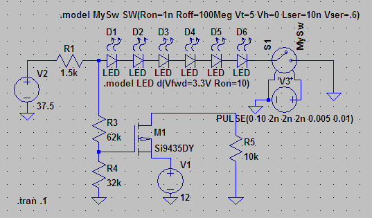
A suitable method to sense when some LEDs in a garage door opener are illuminated. A power source, potentially the same as Vout, connects to a 1.5 kΩ resistor, which then connects to six LEDs followed by a transistor....
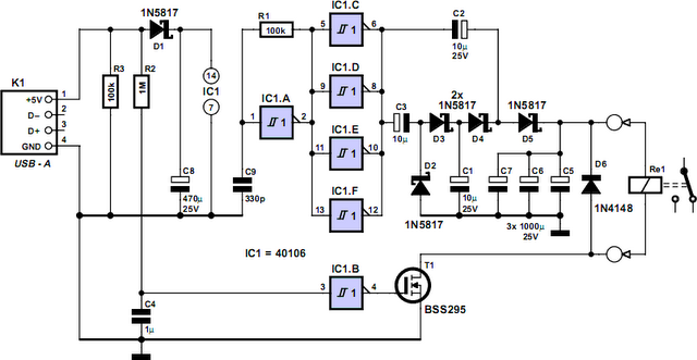
How often does it happen that a user shuts down Windows and then forgets to turn off the computer? This circuit automates that process. After Windows is shut down, a click occurs a second later, disconnecting the PC from...
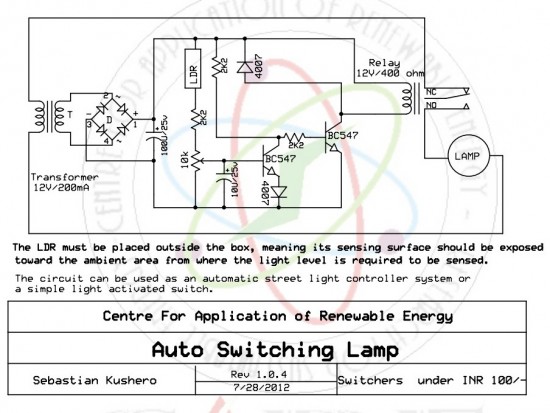
The circuit is designed to switch off a specific lamp or a group of lamps based on varying ambient light levels. Once constructed, it will turn off a lamp at dawn and turn it on at dusk. The power...
Operating high-beam headlights while driving on highways can significantly enhance visibility; however, it poses a blinding risk to other drivers. This straightforward circuit can be integrated into the headlight switch to facilitate automatic switching between high and low beam...
Switch mode circuits can implement a lead acid battery charger more efficiently. It can be constructed using the bq24105 battery charger controller. The bq24105 was originally designed to charge single, two, or three-cell Li-polymer and Li-ion battery packs. However,...
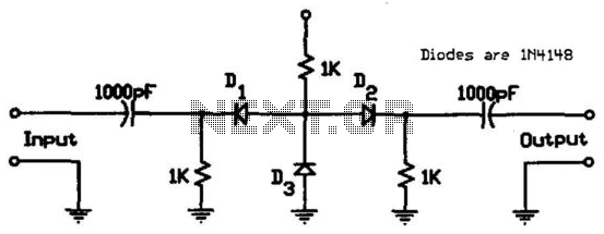
This circuit utilizes low-cost IN4148 diodes and demonstrates approximately 1.5 dB insertion loss across the frequency range of 10 to 1000 MHz with a few volts of negative bias. Under these conditions, diode D3 conducts while diodes D1 and...